OmniView® PRO3 PS/2 KVM Switch User Manual F1DA104Qea F1DA108Qea F1DA116Qea
Table of Contents 1. Introduction ...................................................................................... 1 Package Contents ......................................................................2 2. Overview .......................................................................................... 3 Feature Overview ........................................................................3 Equipment Requirements ............................................................
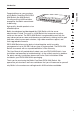
Introduction Belkin has designed and developed this KVM Switch with the server administrator in mind. The result is a KVM Switch that surpasses any other switch on the market. The PRO3 KVM Switch is engineered to work with the most advanced server-room and laboratory environments, offering intuitive port indicators, direct-access port selectors, high video resolution support, and flash-upgradeable firmware.
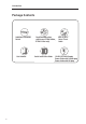
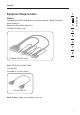
Introduction Package Contents ������������� OmniView PRO3KVM Switch ����������� User Manual ����������� 2 ���������� Rack-MountBrackets withScrews (F1DA108Qea, ������������� F1DA116Qea only) ������������������ �������������� Quick Installation ������ Guide ������������������ ������������ DB9-to-RJ11 ������������� Serial Flash Cable����� 12V DC,1A Power Supply ������� Power Cable with Schuko plug ��������������� Power Cable with UK plug
Overview 1 • Hot Keys 2 Hot-key functionality allows you to select a desired port using designated key commands. By using a simple hot-key sequence on your keyboard, you can select one server from as many as 256 servers, instantaneously. • AutoScan The AutoScan feature allows you to set your PRO3 KVM Switch to scan and monitor the activities of all connected servers, one by one. The time interval allotted for each server can be adjusted through the On-Screen Display (OSD) menu.
Overview • LED Display An LED display on the front panel of the PRO3 KVM Switch serves as a status monitor. An LED above each direct-access port selector illuminates to indicate that the console currently controls the corresponding server. As a port selector is pushed, the LED above it will light up. A flashing port LED indicates that there is no server connected to that port.
Overview 1 Cables: 2 Connecting the PRO3 KVM Switch to a server requires a Belkin Dual-Port Micro-Cable Kit. Belkin Dual-Port Micro-Cable Kits: F1D9400-XX (PS/2-style) 3 4 5 6 7 8 ����������������������� Belkin PRO3 Daisy-Chain Cable: F1D108-CBL (Available in a 2 feet version) ������������� Note: Product codes and availability may vary.
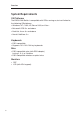
Overview System Requirements OS Platforms The PRO3 KVM Switch is compatible with CPUs running on, but not limited to, the following OS platforms: • Windows® NT®, 2000, XP, Server 2003, or VistaTM • Microsoft® DOS 5.x and above • Red Hat® Linux® 8.x and above • Novell® NetWare® 5.
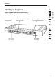
Overview 1 Front View of the PRO3 KVM Switch: 2 (F1DA108Qea) 3 ��������������� ����������������� ������������������� ������������������ ���������������������������� 4 5 6 7 8 ��������������� ������������� ������������ �������������� 7 section Unit Display Diagrams
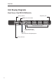
Overview Unit Display Diagrams Back View of the PRO3 KVM Switch: �������������� ������������� ���������������������� ����������������������� ������������������ ��������������������� �������� ������������������������������ ��������������� 8
Overview Specifications 1 F1DA104Qea, F1DA108Qea, F1DA116Qea Enclosure: Metal enclosure with high-impact plastic faceplate Power: 12V DC, 1A power adapter, center-pin-positive polarity Daisy-Chain: Maximum of 16 OmniView KVM Switches No. of Servers Supported: 4, 8, and 16 respectively for 4-, 8-, and 16-port models (256 servers max. via daisy-chaining) Monitors Supported: CRT and LCD (with VGA support) Max.
Installation Pre-Configuration Where to Place the PRO3 KVM Switch The enclosure of the PRO3 KVM Switch is designed for stand-alone or rack-mount configuration. The 8- and 16-Port PRO3 KVM Switches are natively rack-mountable in standard, 19-inch server racks. Rack-mount hardware is included with these Switches for a sturdy rack installation. An optional OmniView Rack-Mount Kit (F1D005) is available for use with the 4-Port PRO3 KVM Switch.
Installation Mounting the PRO3 KVM Switch 1 Bracket Installation (F1DA108Qea and F1DA116Qea) 2 Step 1 Determine how far you would like the PRO3 KVM Switch to protrude from the rack. Select a bracket-hole scheme. Step 2 Attach the bracket to the side of your PRO3 KVM Switch using the Phillips screws provided. (Refer to diagram below.) 3 4 5 6 7 8 Step 3 Mount the PRO3 KVM Switch to the rack-rail assembly. (Refer to diagram below.
Installation Optional Bracket Installation (F1DA104Qea) The PRO3 4-Port KVM Switch can be installed into a 19-inch server rack using an optional OmniView Rack-Mount Kit (F1D005). Step 1 Attach the rack-mount bracket to your 4-Port PRO3 KVM Switch using the Phillips screws provided. (Refer to diagram below.
Installation Step 2 Mount the 4-Port PRO3 KVM Switch to the rack-rail assembly. (Refer to diagram below.) 1 2 4 5 6 Note: If this PRO3 KVM Switch will be daisy-chained to another KVM switch, set the BANK address prior to installing on a rack. Refer to the section titled “Connecting Multiple PRO3 KVM Switches (Daisy-Chaining)” in this User Manual. Your PRO3 KVM Switch is now mounted securely to the rack and you are ready to connect the console.
Installation Connecting the Console to the PRO3 KVM Switch Step 1 Connect the VGA monitor cable to the HDDB15 female port on the back of the PRO3 KVM Switch in the “Console” section. (Refer to diagram below.) Step 2 Connect the PS/2 keyboard cable to the keyboard port on the back of the PRO3 KVM Switch in the “Console” section. (Refer to diagram below.) Step 3 Connect the PS/2 mouse cable to the mouse port on the back of the PRO3 KVM Switch in the “Console” section. (Refer to diagram below.
Installation 1 2 Your PRO3 KVM Switch is now installed and you are ready to connect your servers. 4 5 Connecting PS/2 Servers to the PRO3 KVM Switch 6 Step 1 7 Step 2 8 Make sure your server is powered off. Using the Belkin Dual-Port Micro-Cable Kit for PS/2 (F1D9400-XX), connect the VGA connector to the monitor port on your server. (Refer to diagram below.) Step 3 Connect the PS/2 mouse and keyboard connectors to the mouse and keyboard ports on the server. (Refer to diagram below.
Installation Step 4 Connect the Belkin Dual-Port Micro-Cable Kit for PS/2 to the desired host ports on the PRO3 KVM Switch. (Refer to diagram below.) Step 5 Power up your server. Step 6 Repeat Steps 1 through 5 for each additional PS/2 server you wish to connect. Note: This KVM Switch does NOT support USB connection to servers.
Installation Connecting Multiple PRO3 KVM Switches (Daisy-Chaining) Note: Your PRO3 KVM Switch is backward-compatible with Belkin OmniView PRO2 KVM Switches with standard cabling (F1DA104Tea, F1DA108Tea, F1DA116Tea). In a daisy-chain configuration, the PRO3 KVM Switch with microcabling (F1DA104Qea, F1DA108Qea, F1DA116Qea) must be designated as the primary KVM switch. (Refer to the diagram below.
Installation How to Assign a BANK Address All PRO3 KVM Switches feature a “BANK DIP” switch. The “BANK DIP” switch is used to assign the proper BANK address to each PRO3 KVM Switch. • For a single-unit configuration, set the “BANK DIP” switch on the PRO3 KVM Switch to the “primary” (BANK address 00) setting. This is the factory default setting. • For a multi-unit configuration, the “BANK DIP” switch on the primary KVM switch must be set to “BANK address 00”.
Installation Example of Daisy-Chain Configuration 1 2 Primary unit (BANK 00) 3 4 Secondary unit (BANK 01) cable 2 5 6 Secondary unit (BANK 02) cable 3 Secondary unit (BANK 03) 7 8 Getting Started: Step 1: Make sure that all servers and PRO3 KVM Switches are powered off and that each PRO3 KVM Switch has been assigned a unique BANK address. Step 2: Place all primary and secondary KVM switches in the desired location.
Installation Connecting the Primary and Secondary KVM Switches: Step 1 Using the Daisy-Chain Cable (F1D108-CBL), connect one end to the “Daisy-Chain In” port on the primary KVM switch (BANK 00). Step 2 Connect the other end of the Daisy-Chain Cable (F1D108-CBL) to the “Daisy-Chain Out” port of the first secondary KVM switch (BANK 01).
Installation Connecting the Servers: Step 1: Step 2: Power up the secondary KVM switches sequentially, beginning with the highest BANK, by connecting each unit’s power supply. Each KVM switch should display its corresponding BANK-address number as it is powered up. Step 3: Power up the primary switch. You should see the primary KVM switch light up and display the digits “00”, indicating its BANK address.
Installation Powering Up the Systems Verify that all servers connected to the PRO3 KVM Switch are powered on. If any connected servers have not been powered on, it is okay to do so at this time. The PRO3 KVM Switch emulates both a mouse and keyboard on each port and allows your server to boot normally. The server connected to Port “1” will be displayed on the monitor. Check that the keyboard, monitor, and mouse are working normally.
Using your PRO3 KVM Switch Selecting a Server or BANK Using Hot-Key Commands 2 3 4 5 Switch to the next or previous port with simple, keyboard hot-key sequences using the “Scroll Lock” key, and either the “Up” or “Down” arrow keys. To send commands to the PRO3 KVM Switch, the “Scroll Lock” key must be pressed twice within two seconds. The PRO3 KVM Switch will beep, confirming that it is in hot-key mode. Next, press the “Up” arrow key and the PRO3 KVM Switch will switch to the previous port.
Using your PRO3 KVM Switch With a daisy-chain switch configuration, you can switch between BANKs (KVM switches) by pressing “Scroll Lock”, “Scroll Lock”, “Page Up”, to switch to the previous BANK. Press “Scroll Lock”, “Scroll Lock”, “Page Down”, to switch to the next BANK. ����� �� ����� ���� With a daisy-chain switch configuration, you can switch directly to any port on any BANK by pressing “Scroll Lock”, “Scroll Lock”, BANK address, and port number.
Using your PRO3 KVM Switch Selecting a Server Using Direct-Access Port Selectors Selecting a BANK Using Scroll Buttons Pressing the “BANK +” and “BANK –” scroll buttons on the primary KVM switch will allow you to switch between the daisy-chained PRO3 KVM Switches. Pressing both buttons simultaneously will reset the PRO3 KVM Switch. The “BANK +” button will take you to the next BANK.
Using your PRO3 KVM Switch AutoScan Mode The AutoScan feature allows you to set your PRO3 KVM Switch to scan and monitor the activities of all connected servers one by one. The PRO3 KVM Switch remains on one server for a preset number of seconds, before switching to the next server. The time interval allotted for each server can be adjusted through the OSD menu (see the “Scan Time” section). When the PRO3 KVM Switch is in AutoScan mode, it is also in view-only mode.
Using your PRO3 KVM Switch On-Screen Display (OSD) 1 The OSD allows you to switch servers, assign names to your servers, start and stop the AutoScan feature, set the desired scan-time interval for AutoScan, enable the password security feature, and program hot keys. To access the OSD menu, press “Scroll Lock”, “Scroll Lock”, and the space bar. Immediately, the OSD screen will appear.
Using your PRO3 KVM Switch To switch servers using the main OSD menu, use the arrow keys on your keyboard to navigate to the desired server, and press the “Enter” key. A “ ” symbol indicates which server is currently being accessed on your console. To select a different BANK, press the “Page Up” or “Page Down” key to select the next BANK or the previous BANK. Main Menu Page The following “Main Menu” options are available only to the administrator.
Using your PRO3 KVM Switch The default language is set to English. To designate a different language, use the arrow keys to navigate to the desired language field, and then press “Enter” to select and save the entry. Port Name Edit 1 2 3 User Setting 4 This option allows you to specify an administrator/user name and passwords to prevent unauthorized users from accessing the OSD and KVM Switch. One administrator and eight users can be stored.
Using your PRO3 KVM Switch Access List This feature allows you to discretely specify the user access at a port level. Only the administrator can set up the access list. The column on the left lists the port names. The users are listed by their number (1 to 8). Navigate to the user and port, and press the “Enter” key to enable/deny the access right for each user and port combination. “X” represents access is denied and “O” represents access is enabled.
Using your PRO3 KVM Switch Keyboard Hot-Key-Command Shortcuts 1 Below is a complete list of hot-key commands that can be used for your PRO3 KVM Switch: 2 Command Function Space Bar Activate OSD Next host [01,02.,,,16] port Non-daisy-chain KVM switch [00,01.,,,15] BANK Daisy-Chain Config: First and second digit specifies BANK [01,02.
Using your PRO3 KVM Switch Updating Firmware The PRO3 KVM Switch features flash-upgradeable firmware to ensure compatibility with the latest devices and servers. Firmware upgrades are free for the life of your PRO3 KVM Switch. To update your firmware, download the appropriate firmware file and utility from www.belkin.com/support/. The utility will guide you through the process of updating the firmware on your PRO3 KVM Switch.
Using your PRO3 KVM Switch 4. Run “BELKIN Firmware Upgrade Utility.exe”. Click “Browse” to select the FW upgrade file. Make sure the Comm-port setting matches the port where the Serial Flash Cable is connected. 1 2 3 5 6 7 5. Apply power to the PRO3 KVM Switch. The KVM Switch will enter into flash-upgrade mode and wait for the data to upgrade. 8 6. Click “Write Flash” to start the upgrade. The upgrade process takes about six seconds.
Frequently Asked Questions Q: Which operating systems does the PRO3 KVM Switch support? A: The PRO3 KVM Switch will support any operating system that runs on a PS/2 platform. Operating systems include, but are not limited to, DOS; Windows 2000, NT®, XP, Server 2003, Vista; and Linux. Q: Does the PRO3 KVM Switch support USB mice and keyboards? A: No, the PRO3 KVM Switch supports only PS/2 devices on the console. For USB console support, use Belkin models: F1DA104Zea, F1DA108Zea, F1DA116Zea.
Frequently Asked Questions Q: Do I have to install any software to use the PRO3 KVM Switch? A: No, the PRO3 KVM Switch does not require any drivers or software to be installed in your servers. Simply connect all your servers to the Belkin KVM Cable Kits, and then attach one keyboard, monitor, and mouse to the console port, and it is ready for use. Q: Does the PRO3 KVM Switch require an AC adapter? A: Yes, the PRO3 KVM Switch requires a 12-volt DC, 1-Amp power adapter in order to function properly.
Troubleshooting My server does not boot up when connected to the PRO3 KVM Switch, but works fine when I connect the keyboard, video, and mouse directly to the server. • Make sure that the keyboard and mouse cables are connected tightly between the Server Interface Module and the server. • Check that the keyboard and mouse cables are not crossed. • Check the cable connections. I am getting ghosting, shadowing, or fuzzy images on my monitor.
Troubleshooting The mouse is lost when I switch to a different port. • Check that the mouse you are using is connected properly to the console port of the PRO3 KVM Switch. 1 • Tighten any loose cable connections. 2 • If you are using a mouse driver that was included with your mouse, uninstall it and install the standard Microsoft mouse driver. 3 • Make sure the mouse works when directly plugged into the server.
Glossary The following definitions are used throughout this User Manual. AutoScan: A mode of operation where the KVM switch scans from one port to another, on an ongoing basis, as configured by the user. BANK: The address of a daisy-chained KVM switch (00–15), set by the DIP switch. Console: The all-in-one term for the keyboard, video monitor, and mouse connected to a KVM switch. Console Port: Receptors for the console to connect to the KVM switch.
Information FCC Statement 1 DECLARATION OF CONFORMITY WITH FCC RULES FOR ELECTROMAGNETIC COMPATIBILITY 2 We, Belkin International, Inc., of 501 West Walnut Street, Compton CA 90220, declare under our sole responsibility that the products: F1DA104Q, F1DA108Q, F1DA116Q 3 to which this declaration relates: Comply with Part 15 of the FCC Rules.
Information theft, normal-use wear and tear, erosion, depletion, obsolescence, abuse, damage due to low voltage disturbances (i.e. brownouts or sags), non-authorized program, or system equipment modification or alteration. How to get service. To get service for your Belkin product you must take the following steps: 1. Contact Belkin International, Inc., at 501 W. Walnut St., Compton, CA 90220, Attn: Customer Service, or call (800)-223-5546, within 15 days of the Occurrence.
41
OmniView® PRO3 KVM Switch Belkin Tech Support UK: 0845 607 77 87 Europe: www.belkin.com/support Belkin Ltd. Express Business Park Shipton Way, Rushden NN10 6GL, United Kingdom +44 (0) 1933 35 2000 +44 (0) 1933 31 2000 fax Belkin B.V.