
User manual


1918
1
2
3
4
5
6
7
8
section
1918
Installation
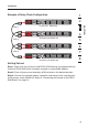
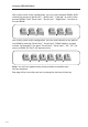
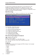
Example of Daisy-Chain Configuration
cable 1
cable
2
cable
3
Primary unit (BANK 00)
Secondary unit (
BANK 01)
Secondary unit (
BANK 02)
Secondary unit (
BANK 03)
Getting Started:
Step 1: Make sure that all servers and PRO3 KVM Switches are powered off and
that each PRO3 KVM Switch has been assigned a unique BANK address.
Step 2
: Place all primary and secondary KVM switches in the desired location.
Step 3
: Connect the console monitor, keyboard, and mouse to the console ports
of the primary switch (BANK 00). Refer to “Connecting the Console to the PRO3
KVM Switch” on page 14.