OmniView ™ KVM Switch with Micro-Cabling Technology Control up to 16 servers from up to two consoles • Expandable to up to 256 from up to four consoles User Manual ENTERPRISE Quad-Bus Series F1DE108C F1DE116C F1DE208C F1DE216C
TABLE OF CONTENTS Introduction Overview Feature Overview . . . . . Equipment Requirements Operating Systems . . . . Specifications . . . . . . . Unit Display Diagrams . . . . . . . . . . . . . . . . . . . . . . . . . . . . . . . . . . . . . . . . . . . . . . . . . . . . . . . . . . . . . . . . . . . . . . . . . . . . . . . . . . . . . . . . . . . . . . . . . . . . . . . . . . . . . . . . . . . . . . . . . . . . . . . . . . . . . . . . . . . . . . . . . . . . . . .
INTRODUCTION Congratulations on your purchase of this Belkin OmniView ENTERPRISE Quad-Bus Series KVM Switch with Micro-Cabling Technology (the Switch). Our diverse line of KVM solutions exemplifies the Belkin commitment to delivering high-quality, durable products at a competitive price. Designed to give you control over multiple computers and servers from up to four consoles, the Switch comes in a variety of capacities suitable for all configurations, large or small.
OVERVIEW Feature Overview Quad-Bus Technology Multiple Switches can be daisy-chained together to allow you to expand up to a maximum of four consoles to simultaneously control up to 256 computers. Integrated Dual-Console Support* You can connect two consoles to simultaneously control up to 256 computers.
OVERVIEW Reprogrammable Hot Key Initiator Sequence The Switch allows you to select up to six alternate keys to initiate hot key commands; this creates compatibility with keyboards that either do not feature identical keys or that may have programmed the identical keys to perform other functions. These settings can be configured through the IntelliView OSD. For more information, please refer to the “IntelliView OSD Features” section of this manual on pages 22 and 23.
OVERVIEW Equipment Requirements Cables To connect the Switch to a computer requires a specialized Belkin ENTERPRISE Quad-Bus Series KVM Cable. For PS/2 computer connection, please use F1D9400-XX. For USB computer connection, please use F1D9401-XX. To connect multiple BANKs together, a specialized Belkin ENTERPRISE Quad-Bus Series Daisy-Chain KVM Cable is required.
OVERVIEW Specifications Part No.: F1DE108C, F1DE116C, F1DE208C, F1DE216C Power: 100-240–264VAC @ 47–63Hz, single phase, 0.25A @ 117VAC, 0.15A @ 240VAC Daisy-Chain: Maximum of 16 BANKs, including 4 consoles Max. Number of PCs: 8 per BANK = 128 total (F1DE108C and F1DE208C), 16 per BANK = 256 total (F1DE116C and F1DE216C) Keyboard Emulation: PS/2 & USB Mouse Emulation: PS/2 & USB Monitors Supported: VGA, SVGA, MultiSync, LCD monitors that accept analog input Max.
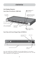
OVERVIEW Unit Display Diagrams Console LED to indicate that this BANK is a Primary console Front View of the Switch (F1DE216C) 7-segment LED for selected BANK address identification (in daisy-chain mode) Manual BANK scroll buttons Auto-Scan Flip-down front fascia LEDs for selected port and console identification Dual manual direct-access port selectors Manual BANK scroll buttons AutoScan button with LED to indicate AutoScan Mode is active Front View with Fascia Flipped Down (F1DE216C) Flash-upgrade p
OVERVIEW Front View with Fascia Flipped Down (F1DE108C) Flash-upgrade port, USB Type B Reset button BANK selection DIP switch Flip-down front fascia Back View of the KVM Switch (F1DE208C) Console 1 Console 2 (on F1DE208C and F1DE216C) 4 high-density, 50-pin, SCSI 2-style computer ports, each supporting 2 servers (on the F1DE108C and F1DE208C) Video Console ports VGA 8 high-density, 50-pin, SCSI 2-style computer ports, each supporting 2 servers (on the F1DE208C and F1DE216C) Daisy-chain port, In H
INSTALLATION Pre-Configuration The enclosure of the Switch is designed for desktop or rack-mount configuration. The Switch is rack-mountable in standard 19-inch server racks. Rack-mount hardware is included with these Switches for a sturdy rack installation. Anti-skid feet are included for stable desktop configurations.
INSTALLATION 1. Remove the brackets from the box. 2. Align the bracket with the front of the Switch for flush installation in your rack. 3. Attach the bracket to the side of your Switch with the screws provided. 4. Mount the Switch to the rack rail assembly. *** Cautions and Warnings *** Before attempting to connect anything to the Switch or your computer(s), please ensure that all your computer equipment and devices are powered off.
INSTALLATION 2. Using the OmniView ENTERPRISE Quad-Bus Series Dual-Port PS/2 KVM Cable (F1D9400-XX), connect the high-density, 50-pin, SCSI 2-style connector to a free Switch port, starting with the port for the first two computers. (For best results, screw the connectors into the Switch and the computer, when possible.) Hosts 1 & 2 Hosts 3 & 4 Hosts 5 & 6 Hosts 7 & 8 3.
INSTALLATION Connecting Computers to the Switch (USB Connection) 1. Attach the IEC power cable to the power connector located on the rear of the Switch. Hosts 1 & 2 Hosts 3 & 4 Hosts 5 & 6 Hosts 7 & 8 2. Using the OmniView ENTERPRISE Quad-Bus Series Dual-Port USB KVM Cable (F1D9401-XX), connect the high-density, 50-pin, SCSI 2-style connector to a free Switch port, starting with the port for the first two computers.
INSTALLATION 4. Boot the computer you wish to connect via USB, as you would normally, with the keyboard, mouse, and monitor connected directly to the computer. 5. Your computer will detect the Switch as a generic mouse and keyboard.
INSTALLATION 3. Connect the PS/2 or USB keyboard to the appropriate port on the back of the Switch in the “Console” section (the purple PS/2 port). 4. Connect the PS/2 or USB mouse to the appropriate port on the back of the Switch in the “Console” section (the green PS/2 port). 5. Repeat steps 1–4 above if you are connecting a second console.* 6. Power on the Switch. 7. Boot all of your host computers.
INSTALLATION DIP Switch Configuration Chart 1 DIP SWITCH # 2 3 4 BANK ADDRESS DOWN DOWN DOWN DOWN BANK 00 (Default) UP DOWN DOWN DOWN BANK 01 PRIMARY/SECONDARY DOWN UP DOWN DOWN BANK 02 SECONDARY UP UP DOWN DOWN BANK 03 SECONDARY DOWN DOWN UP DOWN BANK 04 SECONDARY UP DOWN UP DOWN BANK 05 SECONDARY DOWN UP UP DOWN BANK 06 SECONDARY UP UP UP DOWN BANK 07 SECONDARY DOWN DOWN DOWN UP BANK 08 SECONDARY UP DOWN DOWN UP BANK 09 SECONDARY DOWN UP DOWN UP B
INSTALLATION 3. Connect the console monitor, keyboard, and mouse to the console ports of the primary Switch(es), as previously described for standalone units, skipping steps 5 and 6.* Hosts 1 & 2 Hosts 3 & 4 Hosts 5 & 6 Hosts 7 & 8 Hosts 1 & 2 Hosts 3 & 4 Hosts 5 & 6 Hosts 7 & 8 *Dual-console support available on 2x8 and 2x16 models only. 4. Connect the computers to the Switch as previously described for standalone Switches.
INSTALLATION Connecting the Daisy-Chain Cable: 5. Begin with BANK 00. Using the Daisy-Chain Cable (F1D9402-XX), connect one end to the “Daisy-Chain OUT” port on the first Switch. 6. Connect the other end of the Daisy-Chain Cable to the “Daisy-Chain IN” port of the next Switch. Note: It does not matter which unit is the primary unit, only that they are connected OUT-to-IN or IN-to-OUT. Adding Additional Units: 7.
INSTALLATION 9. If the primary BANK is set to address 00, the KVM administrator must configure the Switch for daisy-chain usage. To do this, take the following steps: (Note: You may see lines across some of the consoles, which is normal since it is in an invalid configuration until the “Daisy-Chain this Switch” option is activated). a) Open the OSD by pressing the CTRL key twice, then the space bar, and enter Setup. b) Go to the Options page, select the “Advanced” button.
USING YOUR SWITCH Now that you have connected your consoles and computers to your Switch, it is ready for use. You can select connected computers by the direct-access port selectors, located on the front panel of the Switch, hot key commands, or the On-Screen Display. Note: For hot keys (e.g. up and down arrows) and AutoScan, the order of progression, when switching from one computer to the next, is dictated by the order of the computers in the list box, on the Main page of the OSD.
USING YOUR SWITCH Daisy-Chain Configuration • The 7-segment display of a secondary Switch will always display its BANK address. All other buttons and LEDs on secondary BANKs will be disabled. Static Mode (Idle) • The 7-segment LEDs will display the current BANK ID. • The Port Selection and Shift LEDs will be off. • The Console LED will be lit, indicating that this Switch is a console. The Switch will go into Select Mode when you press and release any button on the front panel of the console.
USING YOUR SWITCH Selecting a Computer Using Keyboard Hot Key Commands To send commands to the Switch, the Scroll Lock (SL) key must be pressed twice within about half a second (you will hear a beep for confirmation); then, input the key sequence for the specific command (you will have approximately three seconds after the beep to complete each hot key sequence).
USING YOUR SWITCH Using the AutoScan Function from the Front Panel Pressing the AutoScan button on the Switch activates it. In AutoScan Mode, the Switch remains focused on one port for a configured interval (1–99 seconds), before toggling to the next port. AutoScan Mode • AutoScan Mode will continue indefinitely until terminated by pressing any valid hot key sequence, or pressing a button on the front panel. • When the Switch is in AutoScan Mode, it is also in View-Only Mode.
USING YOUR SWITCH IntelliView Graphical On-Screen Display Menu Control The IntelliView Graphical On-Screen Display (OSD) is intended to have a look and feel similar to popular Windows-based operating systems for PCs. To activate the On-Screen Display, press on “Scroll Lock + Scroll Lock + space bar” on your keyboard. (There are other keys that can be substituted for the Scroll Lock key.
USING YOUR SWITCH • Pressing the space bar will activate the OSD control in focus (same as clicking on the control). If the list box is in focus, then pressing the space bar gives the console control of the highlighted computer. • Pressing “Enter” activates the control in focus, if the control is on a button, or inside an edit box, but if the focus is on another type of control (e.g. the list box), the Enter key activates the default control (Close or Exit, depending on the current OSD screen).
USING YOUR SWITCH The Main Page The Main page displays information regarding the current connected severs. At a glance, the user can view the server’s group, computer name, port locations, connection status, and security mode. The Main page could also be used to navigate through the connected server. Group Column The Group column displays the name of the group to which the computer has been assigned.
USING YOUR SWITCH Mouse Column The mouse column displays the status of the current mouse connection, and is updated in real time. If the connection to the computer is via a PS/2 cable, a small mouse icon is displayed. If the mouse connection to the computer is via USB, the USB trident symbol is displayed. If no mouse is detected, the cell will be empty. Security Column The security column displays the security settings for the current user.
USING YOUR SWITCH The Setup Page The Setup page is only available to the Admin user and is used to set the group name, computer name, and computer scan times. The scan time is dependent on the port being scanned, and is global (i.e. it’s independent of the console or user). While scan times are independent of the user, AutoScan will skip computers that the user does not have permission to view. Group Column The Group column displays the name of the group to which the computer has been assigned.
USING YOUR SWITCH Scan Time and “Change All” Button The user can reset the scan time for all computers by entering a value from 1–99 in the edit box and clicking on the “Change All” button. The user will be asked to confirm the action before the new time is applied. Console Column The console currently viewing the computer is indicated in this column. Security Page The Security page allows the administrator to change the computer-access permissions for the Switch’s users.
USING YOUR SWITCH Group Column The Group column displays the name of the group to which the computer has been assigned. The computer list can be sorted on this field by clicking the mouse on the column header. Computer Name Column The Computer Name column displays the name of each connected computer. The computer list can be sorted on this field by clicking on the column header.
USING YOUR SWITCH Password Entry Fields There is a “change password” button associated with each user; clicking the button displays the password entry dialog. The administrator is required to type the password and then confirm it; the new password will not be accepted until the entries match (passwords are up to eight characters long, and case-sensitive). Canceling the change password dialog will return to the Passwords page without changing the existing password.
USING YOUR SWITCH Broadcast Passwords This check box forces all other consoles to overwrite all of their user passwords with the passwords contained in the current console. This makes it simple for the administrator to synchronize the passwords of all consoles (e.g. when adding a new console to an existing configuration). Options Page The controls on this page affect several of the Switch’s features.
USING YOUR SWITCH Display Banner This check box enables a banner to be displayed for system events: pressing a front-panel button, powering-on the Switch, etc. The banner is either always displayed, or displayed for a configured time (1–99 seconds). If the timed selection is enabled, the time input determines how long the banner will remain on-screen after the system event occurs.
USING YOUR SWITCH Advanced Button Activating this button will take the user to the advanced option screen. Disable Viewing When “Disable Viewing” is checked, only another administrator may view channels occupied by the administrator. This function will be active by default in the OSD by design. For security reasons, admin needs to disable this if need be. Daisy-Chain this KVM Checking this box allows Switches set to BANK 00 to communicate with other BANKs in a daisy-chain configuration.
USING YOUR SWITCH Error Messages and Dialogs From time to time, it will be necessary to display messages to the user indicating errors or requesting simple answers to questions. These pop-up screens use the familiar format of title bar and window body, which contains the text of the message. It includes appropriate response controls such as OK and Cancel buttons, based on the nature of the message.
USING YOUR SWITCH The AutoUpdate Firmware Update Utility Updating Firmware The AutoUpdate application is designed to inspect your hardware and guide you through the process of updating the firmware (if necessary) on your Switch. AutoUpdate automatically downloads the best firmware for your device from the Belkin website, or you can download the appropriate file manually by going to our website at belkin.com. The administrator should perform the updates when the KVM Switch(es) is not in use.
USING YOUR SWITCH To start the update process, you must run the AutoUpdate application by selecting “AutoUpdate.exe” from the start menu, or a desktop shortcut. The first screen of the AutoUpdate application will prompt the user to select an automatic or manual update. You should generally select automatic, unless you have a specific reason to do otherwise.
USING YOUR SWITCH Updating Devices via the Web When you start the AutoUpdate application, it searches your computer for devices that support the update process. It also automatically connects to the Web and searches for available updates for the devices that are found. When the application has gathered the relevant information, it lists all of the devices found.
USING YOUR SWITCH Before the AutoUpdate begins, a warning screen will be displayed, informing the user of the risks involved in proceeding with the update, and actions that should be avoided while the update is in progress. Note: It is crucial that the PC and the Switch remain powered-on, and the USB cable remains connected to the PC or the Switch during the update. The user should also avoid using the PC in ways that might interfere with the operations of the AutoUpdate application.
USING YOUR SWITCH When the update is started, a dialog pops up, displaying the file transfer progress for each sub-device, and for the Switch, as a whole. If multiple devices have been selected, the dialog remains up and repeats the update process for each device. When the update is complete, the “Next” button will become active, allowing the user to complete the update. Note: During the AutoUpdate file transfer process, the 7-segment LEDs will display “AU”, indicating AutoUpdate is in progress.
USING YOUR SWITCH The “Advanced” button allows the user to manually force updates into the target device. AutoUpdate does minimal checking to determine whether the selected file is valid in this mode. Belkin does not recommend using Advanced Mode unless directed to do so by Belkin Technical Support. The Advanced button will become active at the same time that the Next button becomes active (when a device is selected and a valid file has been selected).
USING YOUR SWITCH When the update is complete, the Next button will become active, allowing the user to complete the update. If the download fails for any reason, a dialog box will appear with an option to retry the update. If the application has completed successfully, this screen will be displayed. If a reboot is required, that will be indicated on this screen. When you click “Finish”, the AutoUpdate application will close.
USING YOUR SWITCH Completing the Firmware Update The Switch needs to be power-cycled (or reset) after a successful download, so that it can program its internal components. The update process will not be complete until the device has been power-cycled. Warning! If the update process failed or was disrupted, DO NOT power-cycle the device! Resetting the device at this point may cause the Switch to be programmed with corrupted data.
TROUBLESHOOTING I’ve daisy-chained multiple Switches; now I want to add another console. What do I need to do to get it running? • If you want to add your console to a Switch that is already in your daisy-chain with its DIP switches set from 00 through 01, you simply have to connect your monitor, keyboard, and mouse. • Connect the Switch to the computers following the same procedure that you would for a standalone Switch.
TROUBLESHOOTING k) Select “OK” to close the Hot Function Keys dialog box. l) Close the keyboard application. Note: By creating a copy of “Eject this disk” application on your desktop, you can easily map the “Eject this disk” function to the keyboard map. To copy the “Eject this disk” application from within Sherlock, hold down the “Option” key on the keyboard (“Alt” key on PC keyboard) and drag the application from the search result box to your desktop.
GLOSSARY The following definitions are used throughout the manual. AutoScan: A mode of operation where the KVM switch scans from one port to another, on an ongoing basis, as configured by the user. BANK: The address of a daisy-chained KVM (0–15, set by the DIP switch). Console: The all-in-one term for the keyboard, video monitor, and mouse connected to a KVM switch. Console Port: Receptors for the console to connect to the KVM switch.
GLOSSARY Standalone: A single KVM switch that operates independently (not connected to others). Static Mode: The predominant mode of operation of the KVM switch. The switch enters this state whenever it has not received a button press for at least five seconds. OSD: On-Screen Display, a Graphical User Interface that can be used to control and configure the KVM switch. View: When discussing switching between ports, viewing means that the console is receiving video from the computer.
INFORMATION FCC Statement DECLARATION OF CONFORMITY WITH FCC RULES FOR ELECTROMAGNETIC COMPATIBILITY We, Belkin Corporation, of 501 West Walnut Street, Compton, CA 90220, declare under our sole responsibility that the products: F1DE108C F1DE116C F1DE208C F1DE216C to which this declaration relates: Comply with Part 15 of the FCC Rules.
belkin.com Belkin Corporation 501 West Walnut Street Compton • CA • 90220 • USA Tel: 310.898.1100 Fax: 310.898.1111 Belkin Components, Ltd. Express Business Park • Shipton Way • Rushden NN10 6GL • United Kingdom Tel: +44 (0) 1933 35 2000 Fax: +44 (0) 1933 31 2000 Belkin Components B.V. Starparc Building • Boeing Avenue 333 1119 PH Schiphol-Rijk • The Netherlands Tel: +31 (0) 20 654 7300 Fax: +31 (0) 20 654 7349 Belkin, Ltd.