OmniView® SMB KVM-over-IP Switch User Manual F1DP108G F1DP116G
Table of Contents 1. Introduction....................................................................................... 1 Package Contents.......................................................................... 1 2. Overview........................................................................................... 2 Remote-Management Features...................................................... 2 Other Features................................................................................
Table of Contents 5. Using the Switch from a Remote Console....................................... 43 Starting a Remote Session..................................................................... 43 Using the Drop-Down Bar...................................................................... 45 Mouse Configuration and Settings....................................................... 46 Keyboard Configuration and Settings.................................................. 50 Video Configuration and Settings..
Introduction This User Manual provides all the details you’ll need to install and operate your new Switch, in addition to expert troubleshooting advice—in the unlikely event of a problem. For quick and easy installation, please refer to the Quick Installation Guide included in your packaging. We appreciate your business and are confident that you will soon see for yourself why over 1 million Belkin OmniView products are in use worldwide.
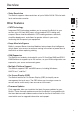
Overview Remote-Management Features • Digital or Local User The Switch allows one user to access and control multiple servers from a local console, or from any remote console over a TCP/IP connection. • Web-Browser Based You can access the Switch from any computer connected to the LAN, WAN, or Internet using Microsoft® Internet Explorer® version 6, 7, 8 (in Compatibility View), or Mozilla Firefox® 3.0.
Overview • Video Resolution Other Features • CAT5 Technology Integrated CAT5 technology enables you to connect the Switch to your servers up to 100 feet (30m) away using standard CAT5 cabling and compact Server Interface Modules. CAT5 cabling reduces cable bulk, simplifies deployment, and allows for greater airflow in your racks, increasing the life span of your equipment.
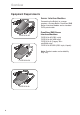
Overview Equipment Requirements Server Interface Modules Connecting the Switch to a server requires a custom Belkin OmniView SMB Server Interface Module and a standard CAT5 patch cable. F1DP101A-AP OmniView SMB Server Interface Modules: F1DP101A-AP (PS/2 style) F1DP101A-AU (USB style) F1DP101A-AL (Legacy Sun™ miniDIN8 style) F1DP101A-AP-8PK (PS/2 style, 8-pack) Note: Product codes and availability may vary.
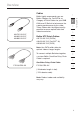
Overview Cables A3L791-XX-YYY A3L850-XX-YYY A3L980-XX-YYY Belkin UTP Patch Cables: A3L791-XX-YYY (CAT5e) A3L850-XX-YYY (FastCAT™ 5e) A3L980-XX-YYY (CAT6) 2 3 4 5 6 Note: Use CAT6 solid cables for optimal video at longer lengths. 7 To connect multiple Switches together, a custom Belkin OmniView Daisy-Chain Cable is required. 8 OmniView Daisy-Chain Cable: F1D108-CBL-XX 1 F1D108-CBL-XX 9 10 (-XX denotes length in feet) (-YYY denotes color) Note: Product codes and availability may vary.
Overview System Requirements Operating-System (OS) Platforms The SMB KVM-over-IP Switch is compatible with CPUs running on, but not limited to, the following OS platforms: • Windows® NT®, 2000, Server 2003, Server 2008, XP, Vista®, or Windows 7 • Microsoft® DOS 5.x and above • Red Hat® Linux® 8.x and above • Sun™ • Novell™ 5.x • Solaris™ 8.
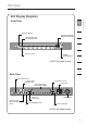
Overview 1 Front View 2 3 AutoScan Button 7-Segment LED for BANK Identification LED Indicators for Port Identification 5 6 BANK 4 Port Selectors Bank Scroll Buttons (F1DP116G model shown) 7 8 9 10 Back View Daisy-Chain Port Console Vga Monitor Port Serial-Device Port AC Power CPU Connections Using CAT5 Cabling ;X`jp :_X`e Console PS/2 Mouse/Keyboard Ports =C8J? C8E Jf CfZXc Ethernet Connection Flash-Upgra
Overview Specifications Part No.: F1DP108G, F1DP116G No. of Users Supported: 1 digital or 1 local No.
Overview Dimensions: (F1DP108G) 17.25 x 1.75 x 7.5 in. (438 x 45 x 190mm) Weight: 2 (F1DP108G) 5.0 lbs. (2.3kg.) (F1DP116G) 5.0 lbs. (2.3kg.) *May be daisy-chained with up to 15 OmniView SMB and PRO2 KVM Switches. OmniView SMB KVM-over-IP Switches may not be daisy-chained together. **Typical bandwidth is defined as typical “non-intensive” administrative use at 16-bit color, 1024x768 resolution. Note: Specifications are subject to change without notice.
Overview SMB Server Interface Module, USB Part No.: F1DP101A-AU Emulation: Keyboard and mouse signals Power: Via attached server Keyboard/Mouse Connection: USB Type A Monitor Connection: HDDB15 male (VGA) Resolution Support: Up to 1600x1200 @ 75Hz Max. Distance Supported: 100 ft. (30m) Weight: 0.25 lbs. (0.11kg.) Unit Dimensions: 1.8 x 3.5 x 0.9 in. (46 x 89 x 23mm) VGA-Cable Length: 8 in. (203mm) USB-Cable Length: 19 in. (483mm) SMB Server Interface Module, Legacy Sun Part No.
Local Installation Pre-Configuration 1 86I* 8VWaZh 2 3 4 HZgkZg >ciZg[VXZ BdYjaZh EH$'! JH7! VcY Hjc hZgkZgh 5 6 C $L6 A6C AdXVa 8dchdaZ (Typical Switch configuration) Where to place the Switch: 7 8 9 10 The enclosure of the Switch is designed for stand-alone or rack-mount configuration. The Switch can be mounted to a standard 19-inch server rack using the included rack-mount brackets and screws.
Local Installation Cable-Distance Requirements (for PS/2, USB, and Sun Servers) VGA signals transmit best up to 100 feet (30m). Beyond that length, the probability of video degradation increases. For this reason, Belkin recommends that the length of the CAT5 UTP cable between the Switch and the connected servers does not exceed 100 feet (30m). Note: The Belkin CAT5 Extender (F1D084) may be used to extend your console (keyboard, mouse, and monitor) by up to 300 feet (91m).
Local Installation Step 1 Mounting the Switch MAC Address Device Number 2 3 4 The Switch includes adjustable mounting brackets ideal for installation in 19-inch racks. The mounting brackets feature three adjustment positions that allow you to set the Switch’s face flush with the ends of the rails, or to extend the Switch past the front of the rails. Please follow these simple steps to achieve the desired adjustment. 1.1 Determine how far you would like the Switch to protrude from the rack.
Local Installation Step 2 Connecting the Console to the Switch 2.1 C onnect your monitor VGA cable to the VGA port on the back of the Switch in the “Console” section. (Refer to diagram below.) ;X`jp :_X`e =C8J? C8E Jf CfZXc 2.2 C onnect your keyboard and mouse PS/2 cables to the PS/2 keyboard and mouse ports on the back of the Switch in the “Console” section. (Refer to diagram below.
Local Installation 2.3 L ocate and connect a cable from your local area network to the RJ45 Ethernet port on the back of the Switch. (Refer to diagram below.) 1 2 ;X`jp :_X`e C8E Jf CfZXc 4 5 2.4 A ttach the power cord to the IEC power jack on the back of the Switch, and power up the Switch. (Refer to diagram below.
Local Installation Step 3 C onnecting Servers to the Switch (PS/2 Connection) 3.1 Make sure your server is powered off. 3.2 U sing the Belkin OmniView SMB Server Interface Module for PS/2 (F1DP101A-AP), connect the VGA connector to the monitor port on your server. (Refer to diagram below.) Server Server Interface Module 3.3 C onnect the PS/2 mouse and keyboard connectors to the mouse and keyboard ports on the server. (Refer to diagram below.
Local Installation 3.4 onnect the Switch to the Server Interface Module using the C included Belkin CAT5e Patch Cable or other CAT5 cable. (Refer to diagram below.) 1 2 4 ;X`jp :_X`e =C8J? :fejfc\ C8E Jf CfZXc 5 6 3.5 Power up your server. 3.6 R epeat steps 3.1 through 3.5 for each additional PS/2 server you wish to connect.
Local Installation Step 3 C onnecting Servers to the Switch (USB Connection) 3.1 Make sure your server is powered on. 3.2 U sing the Belkin OmniView SMB Server Interface Module for USB (F1DP101A-AU), connect the VGA connector to the monitor port on your server. (Refer to diagram below.) Server Server Interface Module 3.3 C onnect the USB connector to an available USB port on the server. (Refer to diagram below.
Local Installation 3.4 C onnect the Switch to the Server Interface Module using the included Belkin CAT5e Patch Cable or other CAT5 cable. (Refer to diagram below.) Your server should recognize your Server Interface Module and automatically install the HID USB driver if necessary. 1 2 4 ;X`jp :_X`e =C8J? :fejfc\ C8E Jf CfZXc 5 6 3.5 R epeat steps 3.1 through 3.4 for each additional USB server you wish to connect.
Local Installation Step 3 C onnecting Servers to the Switch (Sun MiniDIN8 Connection) 3.1 Make sure your server is powered off. 3.2 U sing the Belkin OmniView SMB Server Interface Module for Legacy Sun (F1DP101A-AL), connect the VGA connector to the monitor port on your server. (Refer to diagram below.) Server Server Interface Module 3.3 C onnect the miniDIN8 connector to the miniDIN8 keyboard port on the server. (Refer to diagram below.
Local Installation 3.4 C onnect the Switch to the Server Interface Module using the included Belkin CAT5e Patch Cable or other CAT5 cable. (Refer to diagram below.) 1 2 4 ;X`jp :_X`e =C8J? :fejfc\ C8E Jf CfZXc 3.5 Power up your server. 3.6 R epeat steps 3.1 through 3.5 for each additional Sun server you wish to connect.
Local Installation Step 4 Powering Up the Systems 4.1 I f you have not already done so, power on all servers connected to the Switch (servers can be powered on simultaneously). The Switch emulates both a mouse and keyboard on each port and allows your server to boot normally. The server connected to port 1 will be displayed on the monitor. 4.2 Check that the keyboard, monitor, and mouse are working normally. 4.
Local Installation Daisy-Chaining Multiple KVM Switches (Optional) Note: If you are only installing a single SMB KVM-over-IP Switch, skip to the “Remote Installation” section on page 28. 2 3 4 5 Note: The SMB KVM-over-IP Switch can only function as the primary KVM switch. You cannot daisy-chain two SMB KVM-over-IP Switches together. 6 Note: A Daisy-Chain Cable (F1D108-CBL-XX) is required to daisy-chain each KVM Switch and is available through your Belkin reseller, or online at www.belkin.com (U.S.
Local Installation BANK-DIP-Switch-Configuration Chart (SMB CAT5 KVM Switches) DIP SWITCH# (SMB CAT5) BANK ADDRESS 1 2 3 4 N/A N/A N/A N/A BANK 00 Primary (SMB KVM-over-IP Switch) UP DOWN DOWN DOWN BANK 01 Secondary DOWN UP DOWN DOWN BANK 02 Secondary UP UP DOWN DOWN BANK 03 Secondary DOWN DOWN UP DOWN BANK 04 Secondary UP DOWN UP DOWN BANK 05 Secondary DOWN UP UP DOWN BANK 06 Secondary UP UP UP DOWN BANK 07 Secondary DOWN DOWN DOWN UP BANK 08 Secondary UP
Local Installation Example of Daisy-Chain Configuration ;X`jp :_X`e =C8J? :fejfc\ C8E 1 Jf CfZXc 2 3 4 BANK 01 Secondary Switch 5 6 BANK 02 Secondary Switch BANK 03 Secondary Switch 7 8 9 10 25 section BANK 00 SMB KVM-over-IP Switch
Local Installation Getting Started: 1. ake sure that all servers and Switches are powered off and that each M KVM Switch has been assigned a unique BANK address. 2. lace the SMB KVM-over-IP Switch and all secondary KVM Switches in the P desired location. 3. onnect the console monitor, keyboard, and mouse to the console ports C of the SMB KVM-over-IP Switch. Refer to “Connecting the Console to the Switch” on page 14. Connecting the Primary and Secondary KVM Switches: 26 1.
Local Installation Connecting the servers: onnect all servers to the SMB KVM-over-IP Switch and secondary KVM C Switches. Refer to the “Connecting Servers to the Switch” section on page 16 for instructions. 2. ake sure that the power adapter is connected to the SMB KVM-over-IP M Switch and that the Switch is powered on. You should see the Switch light up and display the digits “00”, indicating its BANK address. 3.
Remote Installation Step 1 Identifying the IP Address Once your Switch has been connected to your network and is powered up, a Dynamic Host Configuration Protocol (DHCP) server on your network will automatically assign the Switch an IP address, gateway address, and subnet mask. To identify the IP address on your network, use the MAC address or unique device number located on the back of the Switch. If no DHCP server is found on your network, the Switch will boot with the following static IP address: 192.
Remote Installation Step 2 Logging into the Web Interface 1. run Internet Explorer in administrator mode. In order to run Internet Explorer in administrator mode, right-click on Internet Explorer and select “Run as Administrator”. If you are using Internet Explorer 8.0, click the “Compatibility View” icon next to the address bar. Type in the IP Device’s IP address in the address field, using this 1 2 3 format: https://192.168.2.155/. The login page will appear (see Fig. 1).
Remote Installation page (see Fig. 2). Fig.
Remote Installation Step 3 Network Configuration When first connecting to the Switch’s HTTPS configuration page, two browser security warnings may appear. Click “Yes” on both warnings. 1 2 3 Type in a name you would like to assign the Switch. The default device name consists of the letter “D” followed by the 7-digit device number located on the back of the Switch. Required TCP Ports Choose the “Transmission Control Protocol (TCP)” port, and type in the provided field.
Remote Installation Enable DHCP When this box is checked (default setting), a DHCP server on your network is enabled to assign an IP address to the Switch. When this box is not checked (recommended), you can assign a static IP address to the Switch. Set a Static IP If you choose not to use DHCP, uncheck the “Enable DHCP” box, then enter the IP address, subnet mask, and default gateway for LAN, as provided by your network administrator.
Remote Installation Step 4 User Settings In the User-Profile page, you can create and edit up to 25 different user accounts. To open the page, click “User Settings” under “Administration” in the far-left menu (see Fig. 3). 1 2 3 5 6 7 8 9 Fig. 3 User-Profile Page 10 There are three levels of user access: Administrator An administrator has unrestricted access to all windows and settings and can “take over” any active session (see page 43 for more details).
Remote Installation View Only A “view only” user is only allowed to view the screen of the target server without keyboard and mouse control. Only limited options appear, such as “disconnect”. A View Only icon will appear on the viewer’s local mouse pointer to indicate this status. Note: Only one administrator can log in to the Configuration page at a time. The Switch can support up to eight simultaneous viewers to a remote session, but only the administrator can take control of the server.
Remote Installation To edit a user: 1. Select the user from the list. 1 2. lick C . You can now change all the available parameters—user name, permission type, and password. 2 3. Click to save the changes. To delete a user: 1. Select the user from the list. 2. Click 3. Click . to save the changes. 3 4 5 6 7 Blocking a standard user and “View Only” user An alternative to deleting a user is “blocking.
Remote Installation Step 5 Switch Configuration The Switch-Configuration page allows you to specify the KVM Switches daisy-chained to the SMB KVM-over-IP Switch, and to name all connected servers. To open the page, click “Switch Configuration” under “Administration” in the far-left column (see Fig. 4). Fig. 4 Switch-Configuration Page Note: By default, the Switch-Configuration page assumes that all daisy-chained KVM Switches have 16 server ports.
Remote Installation To specify and name servers: lick C next to the Daisy-Chain field and select the KVM-switch configuration that best suits your configuration. 2. lick C . The number of possible connected servers will appear in the Server Name section. 3. hange the name of each connected server by highlighting the server and C typing in a new name. 4. Click . to save the changes. Note: You will need to change the name of every server you want to access.
Remote Installation Step 6 Serial Settings If you have a serial device connected to the Switch, such as a power distribution unit (PDU), you must configure the serial (RS232) settings. To open the Serial-Settings page, click “Serial Settings” under “Administration” in the far-left menu (see Fig. 5). Fig. 5 Serial-Settings Page To configure your serial device: 38 1. Type in the name of the serial device. 2.
Remote Installation Step 7 Security Settings The Security-Settings page allows you to configure security features for the Switch. To open the Security-Settings page, click “Settings” under “Security” in the far-left menu (see Fig. 6). 1 2 3 5 6 7 8 9 Fig. 6 Security-Settings Page 10 You can configure the following security features: Account Blocking Specify the number of invalid login attempts allowed before the user is locked out.
Remote Installation Idle Timeout Select the maximum time allowed for inactivity before the user is disconnected from the remote session. Choose “No Timeout” to disable the Idle Timeout feature. By default, the timeout inactivity period is set to 10 minutes. SSL Certificate You can install your company’s own SSL certificate to protect data transferred over the Internet between your servers and remote console.
Remote Installation Maintenance Firmware Upgrade You can upgrade the Switch’s firmware to take advantage of new features or fixes as they become available. Visit www.belkin.com/support to check for firmware updates. 2 3 1. Download and save the firmware file on the client computer. 4 2. elect “Firmware Upgrade” under “Maintenance” in the far-left menu of the S web interface. The Firmware-Upgrade page will appear (see Fig. 8). 3. 5 Click 4. Click “Start Upgrade”. 6 5.
Remote Installation Restore Factory Settings You can restore the Switch to its original factory settings. This restores the original parameters, resetting all the information added by the administrators, including: network settings, servers, switches, users, and passwords. You also have the option to preserve network settings, as explained below. WARNING! Once data has been reset, it cannot be retrieved. To restore factory settings: 1. elect “Restore Factory Settings” in the far-left menu.
Using the Switch from a Remote Console Starting a Remote Session To start a remote session: t a client computer, open Internet Explorer or Firefox web browser and A type the IP Device’s IP address (https:// IP address). 2. hen the Login screen appears, type in your user name and password, W and click . By default, the user name is “admin” and the password is “SMBremote” (both are case-sensitive). 3.
Using the Switch from a Remote Console Full-Screen Mode You can work on the target server in full-screen mode, just as if you were connected to the server locally. To work in full-screen mode: 1. nsure that the client computer has the same screen resolution as the E target server. 2. ress “F11”. The Internet Explorer window will disappear, leaving the P Internet Explorer menu bar at the top. 3. ight-click the Internet Explorer menu bar and check “Auto-Hide”.
Using the Switch from a Remote Console Using the Drop-Down Bar The quick-access, drop-down bar provides an easy method for changing settings and switching between servers (see Fig. 12). 1 2 3 Fig.
Using the Switch from a Remote Console Mouse Configuration and Settings Mouse-Pointer Alignment When working remotely at the client computer, two mouse pointers will appear: one for the client computer and one for the target server. The client computer’s mouse pointer will appear on top of the target server’s. The mouse pointers should be synchronized (aligned). If they are not synchronized, follow the instructions below. To align mouse pointers: 1. In the quick-access toolbar, click 2.
Using the Switch from a Remote Console Manual Settings You must manually synchronize the mouse pointers if: • the mouse setting on the target server was ever changed, or • t he operating system on the target server is Windows XP, Windows 2003 Server, Linux, Novell®, SCO UNIX, or Sun Solaris™. To manually synchronize mouse pointers: In the quick-access toolbar, click 2. Select “Manual Settings”. The Mouse-Settings box will appear (see Fig. 13). . 2 3 4 5 6 7 8 9 10 Fig. 13 Mouse-Settings Box 3.
Using the Switch from a Remote Console 4. ollow the instructions and set any relevant sliders to the same values as F set in the target server’s mouse properties. Examples: For servers running on Windows XP, go to the Mouse settings in the Control Panel and uncheck “Enhance pointer precision” (see Fig. 14). Fig. 14 Mouse-Pointer Options (Windows XP) or servers running on Windows NT, if mouse properties were F ever changed—even if they were returned to their original state—uncheck “Default”. 5.
Using the Switch from a Remote Console Advanced-Mouse Emulation In the Advanced-Mouse settings, you can set the type of mouse you would like the Switch to emulate. Note: Belkin recommends that you NOT change the advanced settings unless there is erratic mouse behavior (i.e., if the mouse is making random clicks and jumping arbitrarily around the screen). To change the mouse-emulation settings: 1. Click . The Mouse-Emulation box will appear (see Fig. 15). 1 2 3 4 6 7 8 Fig. 15 Mouse-Emulation Box 2.
Using the Switch from a Remote Console Keyboard Configuration and Settings You can define and transmit a keyboard sequence directly to the target server, without affecting the client computer. To transmit a keyboard sequence: 1. In the quick-access toolbar, click 2. Select a key sequence to transmit to the target server. . For example, if you select the “Ctrl-Alt-Del” keyboard sequence for the target server, it will allow you to initiate the server’s shutdown/login process from your client computer.
Using the Switch from a Remote Console 4. elect the desired sequence and click “OK”. The sequence will appear in S the Special-Key-Manager box. 1 5. lick “OK”. The sequence will now appear in the C Keyboard-Key-Sequence list. 2 To record a keyboard sequence: 3 1. In the quick-access toolbar, click 2. Click “Add/Remove”. The Special-Key-Manager box will appear. 3. Click “Record New”. The Add-Special-Key box will appear (see Fig. 17). 4. Assign a name to the key sequence in the Label box.
Using the Switch from a Remote Console Video Configuration and Settings Refresh You may need to refresh the video image when changing the display attributes of a target server. To refresh the video settings: 1. In the quick-access toolbar, click 2. Select “Refresh” or press “Crl+R”. . Manual Video Adjust You may want to manually adjust video to fine-tune the target-server video settings, to adapt to a noisy environment or a non-standard VGA signal, or when using a full-screen DOS/CLI mode.
Using the Switch from a Remote Console 1 2 3 4 6 7 Fig. 18 Manual Video-Adjust Bar 8 9 Auto Video Adjust To adjust the video automatically: 1. Open Internet Explorer (or similar) in the background. 2. In the quick-access toolbar, click 3. Select “Auto video adjust”. 10 . The process will take a few seconds. If the process runs for more than three seconds, there may be an abnormal noise level.
Using the Switch from a Remote Console Performance Settings (Bandwidth) You can adjust the bandwidth settings on the Switch to give you the desired compression and color-support levels for your remote sessions. To change the bandwidth settings: 1. I n the drop-down bar, click on . Select Performance. The performance settings box will appear (see Fig. 19). Fig. 19 Performance-Settings Box 2. 3.
Using the Switch from a Remote Console Selecting a Server The quick-access toolbar allows you to easily select and switch to any server connected to the Switch or daisy-chain configuration. To connect to a different server: 1. ove the cursor to the area above the video screen; the toolbar will M show up. 1 2 3 4 2. I n the quick-access toolbar, click . A list of connected servers will appear (see Fig. 20). If a serial device is connected to the IP Device, it will also appear on the list. 3.
Using the Switch from a Remote Console Additional Features When you click in the quick-access toolbar, a menu will appear. From this menu you can access your connected servers. The menu also provides the following features: • About— verifies the current version of software/firmware of your IP Device. Session Profile • Local Settings— opens the Client-Configuration box. • P ointer Type— lets you change the client-computer mouse pointer to appear as a dot, or to not appear at all.
Using the Switch from a Remote Console Restoring Factory Defaults The “Restore Factory Settings” section below explains how to restore factory settings from the web interface. When you cannot access the system (you have forgotten the user name, IP address, or password), you can restore factory defaults from the Switch. To restore factory defaults: ress and hold down the “Go-Local” button on the back of the IP Device P for five seconds while powering up the IP Device.
Using the Switch from a Local Console Now that you have connected your console and servers to the Switch, it is ready for use. You can select connected servers by using either the front-panel port selectors, the On-Screen Display (OSD), or hot-key commands through the console keyboard. It takes approximately 1–2 seconds for the video signal to refresh after switching servers. Re-synchronization of the mouse and keyboard signals also occurs.
Using the Switch from a Local Console With a daisy-chain switch configuration, you can switch between BANKs (KVM switches) by pressing “Scroll Lock”, “Scroll Lock”, “Page Up”, to switch to the previous BANK. Press “Scroll Lock”, “Scroll Lock”, “Page Down”, to switch to the next BANK. Page U p Page 1 2 3 D ow n 4 5 6 7 8 9 Note: You will have approximately five seconds to complete each hot-key sequence. See page 65 for instructions on how to change the hot-key-initiator key.
Using the Switch from a Remote Console Selecting a Server Using Port Selectors You can directly select which server you wish to control by pressing the port selector next to the corresponding port. The LED will illuminate to indicate the port is currently selected. If you are installing multiple KVM Switches that are daisy-chained, use the BANK scroll keys located on the front panel of the primary KVM Switch to access other servers that are connected to the secondary KVM Switches.
Using the Switch from a Remote Console AutoScan Mode The AutoScan feature allows you to set your Switch to scan and monitor the activities of all connected servers one by one. The Switch remains on one server for a preset number of seconds, before switching to the next server. The time interval allotted for each server can be defined or adjusted through the OSD menu (see the “Scan Time” section). When the Switch is in AutoScan mode, it is also in view-only mode.
Using the Switch from a Remote Console On-Screen Display (OSD) The OSD allows you to switch servers, assign names to your servers, enable and disable the AutoScan feature, set the desired scan-time interval for AutoScan, enable the password security feature, and program hot keys. To access the OSD menu, press “Scroll Lock”, “Scroll Lock”, and the space bar. Immediately, the OSD overlay screen will appear.
Using the Switch from a Remote Console OSD-Menu Keyboard Commands Command Function èê Navigate to different servers in the same BANK Page Up/Page Down Select next or previous BANK Insert Highlight server name for editing Enter Switch servers Tab Open the Function/Help page Esc Exit the OSD 2 3 4 5 6 7 To change the name of a server, use the arrow keys to navigate to the desired server, press the “Insert” key, type in the new name, and press “ENTER” to save the entry.
Using the Switch from a Remote Console Function/Help-Page Keyboard Commands Command Function F4 Initiate AutoScan èê Navigate to the next field Insert Highlight field for editing Esc Return to the main OSD menu F10 Program Monitor-DDC2 settings to all Server Interface Modules Space Change options for selected field Scan This specifies whether the AutoScan feature is enabled or not.
Using the Switch from a Remote Console Hot Key This allows you to select which key will be used to initiate hot-key commands. You have four options to choose from: “Scroll Lock”, “Print Screen”, “Ctrl”, and “F12”. The default key for all hot-key commands is “Scroll Lock” (see “Hot-Key-Command Shortcuts” on next page).
Using the Switch from a Remote Console Hot-Key-Command Shortcuts Below is a complete list of hot-key commands that can be used for your Switch: Command Function Scroll Lock, Scroll Lock, è Switch to PREVIOUS ACTIVE port Scroll Lock, Scroll Lock, ê Switch to NEXT ACTIVE port Scroll Lock, Scroll Lock, Page Up Switch to PREVIOUS BANK (By default, selects first active port on the BANK) Scroll Lock, Scroll Lock, Page Down Switch to NEXT BANK (By default, selects first active port on the BANK) Scroll Lo
Using the Switch from a Remote Console Sun Combo Keys 1 The PS/2 keyboard connected to the Switch does not support the Sun keypad to perform special functions in the Sun-operating-system environment. When a USB or Sun Server Interface Module is connected to a Sun server, the Server Interface Module emulates the Sun keys using a set of key combinations called Combo keys. Please refer to the table below.
Using the Switch from a Remote Console Updating Firmware The Switch features flash-upgradeable firmware to ensure compatibility with the latest devices and servers. Firmware upgrades are free for the life of your Switch. To update your firmware, download the appropriate firmware file and utility from www.belkin.com/support/. The utility will guide you through the process of updating the firmware on your Switch.
Frequently Asked Questions What operating systems does the Switch support? he Switch will support operating systems that run on a PS/2 or USB T platform. Operating systems include, but are not limited to, DOS; Windows NT, 2000, Server 2003, Server 2008, XP, Vista, Windows 7; Sun; Solaris; Novell; and Linux. Does the Switch support Microsoft IntelliMouse®? The Switch supports mice from Microsoft, Logitech , Kensington , etc., and Belkin.
Frequently Asked Questions Does the Switch support Linux? es, the Switch works with Red Hat and other Linux distributions configured Y for PS/2 or USB support. What communication ports does the Switch use so it can be accessed remotely? ive ports have to be open to remotely connect to the Switch. Ports 80 and F 443 are used for standard web communication. Three consecutive ports are used to send the remote video. These can be user-defined. By default, ports 900, 901, and 902 are used.
Troubleshooting Local Console General Problem: My server does not boot when connected to the Switch but works fine when I connect the keyboard, video, and mouse directly to the server. Solution: • M ake sure that the keyboard and mouse cables are connected tightly between the Server Interface Module and the server. • Check that the keyboard and mouse cables are not crossed. • Check the CAT5 cable connection.
Troubleshooting Keyboard Problem: The server does not detect a keyboard and I get a keyboard error reported at boot up. Solution: •C heck that the keyboard cable on the Server Interface Module is completely connected to your server. Tighten any loose connections. • I f you are using the keyboard software that was included with your keyboard, uninstall it and then reinstall the standard Microsof keyboard driver. Mouse Problem: The mouse is lost when I switch to a different port.
Troubleshooting Problem: When I switch from one port to another, mouse movement is completely erratic. Solution: • Make sure you do not have more than one mouse driver installed. Make sure that the driver is either for a standard PS/2 mouse or a Microsoft server-compatible PS/2 mouse. • Make sure you do not have any mouse drivers loaded in your ConfigureSYS or AUTOEXEC.BAT files. • Avoid moving the mouse or pressing the mouse button when switching ports on the Switch.
Troubleshooting Remote Console Problem: The Remote console login page will not display on my browser. Solution: •V erify that you are using Microsoft Internet Explorer 6.0, 7.0, 8.0 (in Compatibility View), Firefox 3.0. • Verify that the ActiveX plug-in is installed and enabled for the web browser. •A firewall may prevent access to the remote console. Verify that default ports 900, 901, and 902 for both HTTP and HTTPS are open.
Troubleshooting Problem: The video quality is bad and/or grainy. Solution: • Use the quick-access toolbar to refresh the video screen. •U se the quick-access toolbar and select “Automated adjust” under “Manual video adjust”. Refer to page 52. Problem: The video performance and/or mouse performance is slow. Solution: • Use the quick-access toolbar to refresh the video screen. •U se the quick-access toolbar and select “Automated adjust” under “Manual video adjust”. Refer to page 52.
Glossary The following definitions are used throughout this User Manual. AutoScan: A mode of operation where the KVM switch scans from one port to another, on an ongoing basis, as configured by the user. BANK: The address of a daisy-chained KVM switch (00–15), set by the DIP switch. Client Computer: The computer being used to access the Switch remotely over a TCP/IP connection. Console: The all-in-one term for the keyboard, video monitor, and mouse connected to a KVM switch.
Glossary KVM: Literally “Keyboard Video Mouse”, this term refers to technology that allows two or more computers to be controlled by one keyboard, video monitor, and mouse; some switches that use KVM technology enable sharing of other peripherals such as audio speakers, microphones, and printers. KVM Switch: A device that allows a user to access and control multiple servers from a single console. It has at least one console port and multiple server ports. MAC: Media Access Control.
Information FCC Statement Declaration of Conformity with FCC Rules for Electromagnetic Compatibility We, Belkin International, Inc., of 501 West Walnut Street, Compton, CA 90220, declare under our sole responsibility that the products: F1DP108G, F1DP116G, to which this declaration relates: Comply with Part 15 of the FCC Rules.
Information purchaser, or if Belkin determines that the Belkin product has been improperly installed, altered in any way, or tampered with. The Belkin Product Warranty does not protect against acts of God such as flood, lightning, earthquake, war, vandalism, theft, normal-use wear and tear, erosion, depletion, obsolescence, abuse, damage due to low voltage disturbances (i.e. brownouts or sags), nonauthorized program, or system equipment modification or alteration. 1 How to get service.
Information This warranty gives you specific legal rights, and you may also have other rights, which may vary from state to state. Some states do not allow the exclusion or limitation of incidental, consequential, or other damages, so the above limitations may not apply to you.
OmniView® SMB KVM-over-IP Switch Belkin Tech Support US: 800-223-5546 ext. 2263 310-898-1100 ext. 2263 UK: 0845 607 77 87 Australia: 1800 235 546 New Zealand: 0800 235 546 Singapore: 65 64857620 Europe: www.belkin.com/support Belkin International, Inc. 501 West Walnut Street Los Angeles, CA 90220, USA 310-898-1100 310-898-1111 fax Belkin B.V. Boeing Avenue 333 1119 PH Schiphol-Rijk, The Netherlands +31 (0) 20 654 7300 +31 (0) 20 654 7349 fax Belkin Ltd.