INSTRUCTION MANUAL 10-001-275 THIS MANUAL IS FOR TECHNICIAN USE ONLY XLS Integrated Pump Controller ™ HUMAN MACHINE INTERFACE (HMI) FOR THE TECHNOFORCE™ BOOSTER SYSTEM TECHNICIAN GUIDE
Acknowledgements All materials ©2014 by Xylem Inc. All rights reserved. No parts of this work may be reproduced in any form or by any means - graphic, electronic, or mechanical, including photocopying, recording, taping, or information storage and retrieval systems - without the written permission of the publisher. Products that are referred to in this document may be either trademarks and/or registered trademarks of the respective owners. The publisher and the author make no claim to these trademarks.
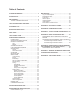
Table of Contents ACKNOWLEDGEMENTS................................................... 2 INTRODUCTION................................................................. 5 HMI OVERVIEW.................................................................. 5 TYPICAL PUMPING OPERATION ................................ 6 TOUCH-SCREEN PANEL OPERATION............................. 6 WEB REPORTS................................................................ 31 Log on to Web Reports.........................................
Table of Figures/Tables Figure 1 Connection for USB Keyboard (c)......................... 6 Figure 2: Start Up Screen.................................................... 6 Figure 3: Basic Booster Home Screen................................ 7 Figure 4: Guest Service Screen.......................................... 7 Figure 5: Supervisor Service Screen................................... 8 Figure 6: Log In Screen....................................................... 8 Figure 7: Log In Keypad..................
Introduction CAUTION: Equipment Damage Hazard This manual is written for Bell & Gossett Technicians and is an introduction to the XLS HMI (Human Machine Interface). The HMI is a browser- based system which allows the user to interact with the settings and reports of the pumping system. This manual only covers the HMI aspect of the system. Please see the TechnoForce Booster Instruction Manual for any questions not related to the HMI.
Typical Pumping Operation Several common control variables including flow, pressure, and level can be used for operating a booster system. Pump starts and stops are based on the changes in these control variables. A VFD (Variable Frequency Drive) is used to regulate the speed of the pumps, replacing the function of a control valve. Pressure recovery can be made smoothly, resulting in power and cost savings.
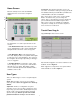
Home Screen Technician: All setup and operation screens are accessible. Technicians must log-in using a password. The default technician password will be provided to the certified installer at the time of installation. Once the startup screen clears the HMI will display the home screen for the configured station. Note: Some values require you to set the “Enable Writes” checkbox before you can change the values.
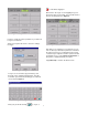
to exit without logging in. Once back to the Log In screen tap [OK] to log in or [Cancel] to abort. If Log in was successful the Service Screen should appear as in Figure 8. Figure 5: Supervisor Service Screen In order to enable all of these parameters you will need to log in as Technician. Tap [Log on/off] from the Service Screen to change User type. Figure 8 : Technician Service Screen Now that you are logged in as a Technician you can view or alter any of the station parameters.
Home Screen Navigation The Booster home screen has been designed to mimic the look of the configured booster and to allow for quick visual cues for ease of navigation. 8 7 9 a. 10 By tapping , in either Idle or Auto Modes, an enhanced screen shown in Figure 11 will appear to set individual pump status. 11 1 2 Figure 11: Pump Switch Screen 4 2.
MODES OF OPERATION The HMI will display various modes of operation with dedicated screens. These modes of operation can be accessed through the interface on the home screen. 1. IDLE MODE will be active when the unit is not in [MANUAL] or [AUTO] and the pumps will not be allowed run. Figure 1 7 : Manual on/off b. The PERCENT SPEED displays the current set speed. By tapping , an Enhanced Screen shown in Figure 18 will appear and allow for manual control of the pump speed and status.
ALTERNATION SET UP The default alternation sequence is set from the factory to alternate the pumps every time a pump is turned off by the system. The control will automatically select the pump with the lowest number of run-hours every time a pump is staged on/off. By tapping [ALTERNATION] an enhanced screen shown in Figure 19 will appear that allows the modification of the alternation sequence for the station.
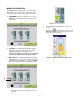
b. User SP field SYSTEM VIEW & TRENDS By tapping By tapping in the “User SP” from the System View you can adjust the system Normal Set Point. from home screen, System View accesses color-coded operational trends or historical data for several system variables such as flow, pressure, speed, and setpoint. c. d e Time Period By tapping [Time Period] from the System View an enhanced screen allows you to set a date and duration for viewing system information.
scaling for the channel. The exception here is the KW reading, which is an absolute number because KW is read directly, rather than scaled. This field shows, from left to right, the current combo (highlighted), start time, psi below setpoint, stop time and psi above setpoint to stop, for each combo. To the right is a table detailing the pumps to run in each combo.
c. The [Ack All] button will clear any alarms that are currently active. d. Tapping [Period], available in ‘Critical – History” and “Non-Critical” modes, will open an enhanced screen shown in Figure 29 to allow for the display of only alarms during a given range. SETPOINTS The [SETPOINTS] tab will take you to the Setpoint detail screen. From this screen you will be able to view the station setpoints along with the current values of certain parameters.
c. “Lockout Setpoint” will display what the Lockout system has identified as the required set point. “Remote (Comm)” enable is the setpoint being communicated by the remote communication system. The enable box must be checked in order for the remote communication system to adjust the system set point. Figure 3 4 : Setpoint Detail C d. Figure 3 6 : Setpoint Detail E This portion of the screen will display the Remote Transducer Settings.
Figure 38: Lockout Screen Figure 40: Parameter Tab in Lockout Setup Individual lockouts may be setup by tapping over each lockout inset. Tapping any inset opens a configuration window. The day, start time, and duration may be entered in the interval tab at the top. In the parameter tab, the combo number, setpoint, and speed can be entered. Tap [Apply] to save settings or [Close] to discard any changes. The Parameter tab enables a user to define Combo number, maximum pressure, and maximum speed in RPM 2.
Verizon: phonenumber@vtext.com 3. [Email Setup] Nextel: phonenumber@messaging.nextel.com US Cellular: phonenumber@email.uscc.net This page allows you to set up email addresses where Alarm and shutdown messages will be sent. These emails will notify the user if the station has shut down or experienced a problem that the site personnel should be aware of. This way the user will be notified immediately in case of a pump station problem. If a fault occurs, an email will be sent to him.
Tap [Set Date] to synchronize HMI & PLC date and time. You will get a pop up message shown below, hit [OK]. Figure 42: Email Settings Occasionally, the settings changes here may require restarting the HMI. Try this if you experience problems getting the test email to work. This can be accomplished through cycling power or by shutting down and restarting the application. Then see appendix “F” for other troubleshooting aids. Figure 4 4 : Sync Pop-up Detail To adjust the totalizers tap [Totalizers].
6. [Tuning] 5. [Security Setup] Tap [Security Setup] from the SERVICE Menu. Tap [Tuning] from the SERVICE Menu. The Tuning screen will allow you to set the PID and speed control settings for station operation. Figure 4 6 : Security Setup Home Screen The Supervisor can change the password assigned to him/her, and set the number of days after which the password expires (in the editable field). To change the password, tap [Change Password] to change the supervisor password.
Low and high flow settings: technician to copy values from one PID group to the other. To copy, select the PID group to copy from and click “Read”, then select the PID group to copy to and press “Write”. The low flow and high flow settings are used together to calculate the proportional and derivative terms at any given time. The low flow settings are what the proportional and derivative terms would be if flow were 0.
Supplemental Control Combo Up (After XL Start): This setting controls the speed the VFD running the main pump will be forced to when a fixed speed lag pump starts. This helps prevent overpressuring by reducing the capacity of the VFD Pump, which is then being provided by the fixed speed pump after it starts. Generally set to 1/3 the value between min speed and 32767.
Trigger Pressure: PM Skip: Line Fill Mode will trigger below this pressure (Percentage of setpoint) when powering up or entering “Auto” from Off mode. Speed step: Controls how much pressure drop will cause the system to automatically skip the PM Pump in the sequence. Fast pressure drop indicates a large demand has suddenly been applied to the irrigation system.
1. 2. 3. 4. 5. Start Pressure: number of seconds the station delays before the start of the specified combo, once ∆P has been reached Start Time: Stop Pressure: number of seconds the station delays before it stops the specified combo, once ∆P has been exceeded. Stop Flow: Stop Time: Tap [Next] to move to the next Field Setup screen Pump Curve Configuration This screen allows you to load/reload the individual pump curves for the station.
have the correct file before selecting [Download to PLC]. Tap [Next] to move to the next System Setup screen. Basic Pump Information The number of pumps can be selected from a drop down menu. Note that this is set from the factory and changing the number of pumps could render the station inoperable if the selection does not match the actual number of pumps. Figure 5 7 : Zone Totalizer Setup The number of zones can also be set from the drop down menu. The name of the flow zone is set here.
Figure 60: Control Options Figure 5 8 : Pump Configuration Combo Options Each pump can be selected from a drop down menu in this screen. It can be assigned a group, type (Main, Jockey, or PM), and number of VFDs that are going to be used. This section allows you to make various selections on control options for the station detailed below.
“Normal Mode Max kW” is the current allowable “Maximum Power” set for the station in under normal operating conditions. Remote Transducers This section will allow you to enable remote transducers that are installed. To adjust the “Enable Remote Sensors” These are the options available for power monitoring. Combo Definitions This screen allows you to checkmark various combo options. ‘PSI Start Enable’ and ‘PSI stop Enable’ are essential.
Figure 6 6 : Flow Totals Overview Figure 64: Alarm Configuration Tap [Next] to successively view the totals for each day, week, month and year. Use the scroll bar to move up and down or left and right. ENERGY The [ENERGY] tab will take you to the Power usage detail screen. From here you will be able to see the totalized values for Flow and KWh in tabular format.
Figure 6 8 : COM Home Screen Figure 7 1 : COM Protocol Selection Protocol settings are then available for editing. Use the Top, Prev, Next and Last buttons to navigate among the pages of the properties for the protocol selected. Press Save for each page as changes are made. Once all the changes are made, press “Set New Protocol”. The HMI will reboot to make the required changes. The station will still operate during this process, but the HMI will not show pressure/flow etc.
TimeOut-End TimeOut-Interval Between Char TimeOut-Wait CTS Typical settings for Modbus TCP are as follows: Page Page Modbus - Link Serial Encapsulation Connection Station ID Protocol Modbus - Modem Configuration Modem Identifier Phone Number Page Page Page Page Page Modbus - Modem Options Enable incoming calls Auto Connect Enable Auto Connect Retry Interval (s) Disconnect if call idle more than...
Typical BacNet communications settings are as follows: Page Page BacNet - Link Serial Encapsulation Link Type Device UDP Port MSTP MAC BacNet - Modem Configuration Modem Identifier Phone Number Page Page Page Page BacNet - Modem Options Enable incoming calls Auto Connect Enable Auto Connect Retry Interval (s) Disconnect if call idle more than...
After the HMI interface opens, the user type (from Guest to Supervisor) may be changed by the standard procedure described for touch panel log in. Web Reports Internet users of the HMI interface can also view and print different reports. There is an Alarms Report, Historical Report, Usage Report, and Factory Reports. The navigation bar allows the user to access each report’s setup screen and print the report.
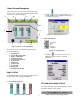
Figure 74: Web Reports Menu Figure 75: Trends View Trend View Alarms Report Select [Trend View] from the Web Reports Menu. Select [Alarms Report] from the Web Reports Menu. There are four key parts to the trends screen. Mean Value Graph and Detail: For each of the key variables (Flow, Pressure, Speed, and Setpoint) the mean values are displayed as a vertical bar graph on the top while the Maximum values are displayed in fields below.
Figure 77: Historical Report Usage Report Select [Usage Report] from the Web Reports Menu. Usage Report allows you to view the totalized flow values for each day, week, month, and year. The table in the middle on the left shows the times or counters when totalizers reset. Table on bottom left shows the number of starts, and runtime hours for each pump. Figure 78: Usage Report Smart Phone and PDA access: A simpler web page is available for smart phone access.
Appendix A–Glossary of Terms The terms used in this manual are defined in the Glossary of Terms. In addition, other industry specific or product-specific terms are included that may be used by technicians or customer service when talking about your pumping system. Across-the-line (XL) Applying 100% of line voltage to a motor during startup and run. A simple large relay with a contact for each power phase (for 3 phase) is used to control the motor OFF/ON.
Filter A device used downstream of the pumps to clean the water being pumped into the irrigation. These devices are typically self-cleaning, but require hardware/software to self-clean. Fixed speed Pumps run at a fixed RPM, defined by the motor windings and the frequency of the line voltage (50/60 Hz). Frequency (Hz) The number of oscillations per second of any system. Typically used to refer to electrical systems, such as AC power line frequency, or variable speed drive output frequency.
Phase monitor A device that analyzes incoming voltage and determines whether all voltage parameters are acceptable and the phase sequence is correct. PLC Programmable Logic Controller. A very robust/rugged computer designed for equipment control in harsh environments. PM pump Pressure Maintenance Pump. Handles very light flow rates and leaks to prevent the main pumps from cycling. Pressure reducing valve (PRV) A control valve designed strictly for maintaining a specific downstream pressure.
Appendix B ─ Networking Options 37
Appendix C–Typical Alarms Configuration Default Alarms / Faults 38
Appendix D – Email Troubleshooting DETERMINING THE IP ADDRESS OF THE SMTP SERVER On your Windows PC, Click “Start”, “Run”, type in “CMD” in the dialog and press enter. You will see a DOS prompt window similar to that below. Type “ping” followed by the server name of your SMTP service. Your email provider will be able to supply these server names as a standard part of the information needed to set up your email for outlook or other email programs.
Look at the line following your command entry, this will contain the IP address of the SMTP server. In this case, smtp.runbox.com is at IP address 87.238.52.70. Double-check the POP3 server for the same IP address. Same procedure, but use your pop3 server name in the ping statement.
TROUBLESHOOTING GENERAL EMAIL FAILURES The following are some common problems encountered when configuring email settings. Double check each setting to ensure the correct information was entered. 1. Attempting to use the server name rather than the IP address in the SMTP field. 2. Using an incorrect IP address - determine the IP address from the procedure above. 3. Entering an invalid user. Make sure the user field matches the account. Also make sure the “From” field matches the user information exactly. 4.
Troubleshooting Email Send Failures The following table gives the number codes associated with failures received after tapping [SEND] to do a test-run of the email addresses and the SMTP: Value Description 0 Success 1 Invalid format for parameter 1 (Subject) 2 Invalid format for parameter 2 (Message) 3 Invalid format for parameter 3 (To) 4 Wrong number of parameters 5 Start Socket error 6 Error getting host IP Address (i.e.
• If successful, be sure and type “quit” . It’s bad form to leave the server hanging though it will reset the session itself. • If you are unable to connect, attempt to Telnet to the POP3 server on port 110. Successful Telnet to the POP3 server but unsuccessful telnet to the smtp server is typical of a port 25 block by the ISP. They often block port 25 to prevent spammers from using home and unwary business accounts for spam generation. A call to your ISP will usually resolve the problem quickly.
Appendix E: Computer Setup and Determining the IP address of your pump station Connecting to the pump station after the hardware is installed is relatively easy. The first step is to connect your PC to the network. This simply means your PC will be connected to the LAN side of the router supplied by Bell & Gossett. Step 2 is to set the IP address of your PC. Click Local Area Connection.
Another window will come up. Select Properties: Highlight Internet Protocol (TCP/IP). If there are two entries, one for v6 and one for v4, select v4 as shown. Then select Properties.
Select “Use the following IP address” Check with your IT department or internet service provider for proper DNS server settings. These should be no different than your settings before installing the router. DETERMINING THE IP ADDRESS: Determining the IP address to use to communicate with your pump station remotely can be as easy as asking your IT professional, or somewhat more complicated, requiring you to access your routers status page.
Select the “Status” page from the menu at the top of the screen. Scroll down the page to the “WAN” status to see the IP address assigned by your Internet service provider. Please note, if your network is more complicated than a simple connection through a cable or DSL modem, please consult your IT department. The procedure outlined above can only supply the IP address of the router, and therefore the IP address of your PC, with reference to the network the router is connected to.
Appendix F – General Networking and Router Configuration Discussion: Regarding the requirement for a fixed IP address: This is not a requirement of the Bell & Gossett control system. This is required so the user attempting to access the system remotely can find the machine on the internet. Without a fixed IP address, the computer is at one of 4,228,250,625 theoretically possible addresses, though usually addresses are assigned within a specific range of a few thousand.
The user would access his station by requesting a web page at http://76.199.50.60 (default port is 80 for HTTP). Note how the pump station router, the last in the line, redirects the port requests to specific device (IP address) at the same port (80). All other routers are just passing along the message, keeping the port #s essentially intact.
Generally, the WAN port of the pump station router is connected directly to the cable or DSL modem, so the complex routing configuration is not required. The pump station router is usually configured as follows: WAN LAN Port Forwarding Pump Station Router 76.199.50.60 (Supplied by internet service provider) 192.168.1.1 80->192.168.1.15:80 81->192.168.1.16:80 82->192.168.1.
Appendix G – Quick Start Guide This guide will provide a Technician the steps needed to start the Technoforce XLS station. Prior to following this guide the station must be mechanically and electrically installed and the system filled with water. All remote sensors, if applicable, should also be installed and calibrated. Please refer to the Station Installation Document and Technician’s IOM for detailed set up for the station. Access This is for operation at the Technician level.
Unit Set-up Prior to starting the Booster you will need to ensure all of your set points are correct. Please note that the Booster station is pre-configured at the factory based on the work order (WO) which is included in your station documentation. 1. 2. 3. 4. Prior to starting your station verify that this information is accurate. On the controller touch screen tap the SERVICE key.
10. The Dynamic Flow Loss Compensation will be set to zero unless specified on the WO. This setting may need to be adjusted while tuning the station. 11. Press the BOOSTER key located at the very top of the screen to return to the main display. ATTENTION: The following steps are going to start the station Unit Start-up 1. From the Booster home screen tap for pump 1. An enhanced screen will appear that will allow you to place the pump in Auto Mode. 2. 3. 4. 5.
9. Ensure that when setpoint is reached and demand is zero, the station will shut down. If not, please review configuration and Technician’s IOM for more detailed trouble shooting. For fine tuning of the system and system setpoints, please refer to your Technician’s IOM.
WARRANTY INFORMATION COMMERCIAL WARRANTY Warranty.
LIMITED CONSUMER WARRANTY Warranty.
Xylem 1) The tissue in plants that brings water upward from the roots; 2) a leading global water technology company. We’re 12,500 people unified in a common purpose: creating innovative solutions to meet our world’s water needs. Developing new technologies that will improve the way water is used, conserved, and re-used in the future is central to our work. We move, treat, analyze, and return water to the environment, and we help people use water efficiently, in their homes, buildings, factories and farms.