INSTRUCTION MANUAL P2003449 REV A Series e-60
Table of Contents Table of Contents 1 Introduction and Safety..............................................................................................................3 1.1 Introduction.......................................................................................................................... 3 1.2 Safety..................................................................................................................................... 3 1.2.1 Safety terminology and symbols...............
Table of Contents 6.3.5 Capscrew torque values............................................................................................ 23 6.3.6 Dealer servicing ......................................................................................................... 23 7 Parts Listings and Cross-Sectional Drawings........................................................................24 7.1 Cross-sectional drawings.........................................................................................
1 Introduction and Safety 1 Introduction and Safety 1.1 Introduction Purpose of this manual The purpose of this manual is to provide necessary information for: • Installation • Operation • Maintenance CAUTION: Read this manual carefully before installing and using the product. Improper use of the product can cause personal injury and damage to property, and may void the warranty. NOTICE: Save this manual for future reference, and keep it readily available at the location of the unit.
1 Introduction and Safety Hazard levels Hazard level Indication DANGER: A hazardous situation which, if not avoided, will result in death or serious injury WARNING: A hazardous situation which, if not avoided, could result in death or serious injury CAUTION: A hazardous situation which, if not avoided, could result in minor or moderate injury Notices are used when there is a risk of equipment damage or decreased performance, but not personal injury.
1 Introduction and Safety Electrical connections Electrical connections must be made by certified electricians in compliance with all international, national, state, and local regulations. For more information about requirements, see sections dealing specifically with electrical connections. Precautions before work Observe these safety precautions before you work with the product or are in connection with the product: • Provide a suitable barrier around the work area, for example, a guard rail.
2 Transportation and Storage 2 Transportation and Storage 2.1 Inspect the delivery 2.1.1 Inspect the package 1. Inspect the package for damaged or missing items upon delivery. 2. Note any damaged or missing items on the receipt and freight bill. 3. File a claim with the shipping company if anything is out of order. If the product has been picked up at a distributor, make a claim directly to the distributor. 2.1.2 Inspect the unit 1. Remove packing materials from the product.
2 Transportation and Storage For questions about possible long-term storage treatment services, please contact your local sales and service representative.
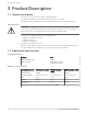
3 Product Description 3 Product Description 3.1 General description The Series e-60 is an in-line mounted centrifugal pump. This pump is available for pipe sizes that range from 1 in to 3 inches. This pump also has available power levels that range from 1/4 to 3 hp and 1750 rpm. Pump application WARNING: California Proposition 65 warning! This product contains chemicals known to the state of California to cause cancer and birth defects or other reproductive harm.
4 Installation 4 Installation 4.1 Preinstallation Precautions WARNING: • When installing in a potentially explosive environment, make sure that the motor is properly certified. • You must ground (earth) all electrical equipment. This applies to the pump equipment, the driver, and any monitoring equipment. Test the ground (earth) lead to verify that it is connected correctly. NOTICE: Supervision by an authorized Xylem representative is recommended to ensure proper installation.
4 Installation 4.1.2 Piping checklist The code for pressure piping, ANSI B31.1, lists types of supports available for various applications. WARNING: • The heating of water and other fluids causes volumetric expansion. The associated forces can cause the failure of system components and the release of hightemperature fluids. In order to prevent this, install properly sized and located compression tanks and pressure-relief valves.
4 Installation Check Explanation/comment Check that new flange gaskets are installed between the flanges of the pump body end suction and discharge pipes. Make sure that these gaskets are clean and grease-free. Suitable fasteners for this connection are supplied in the Xylem fastener pack. Apply a torque of 8 to 11 ft. lbs (11 to 15 Nm) to each of the flange bolts. Both the suction and discharge flanges must be torqued to the same level. Checked 4.1.
4 Installation Figure 4: Vertical mode of discharge Figure 5: Horizontal mode of discharge 4.1.
4 Installation 4.2.1 Wiring diagrams These wiring diagrams are typical and might not be representative for all motor types. Refer to the motor or motor nameplate for specific diagrams. Single-phase motors Single-phase motors are protected with inherent overheating devices and do not require external overload protection. Single-phase motors can operate at either a low voltage (115 V) or a high voltage (230 V).
5 Commissioning, Startup, Operation, and Shutdown 5 Commissioning, Startup, Operation, and Shutdown 5.1 Preparation for startup WARNING: • Failure to follow these precautions before you start the unit will lead to serious personal injury and equipment failure. • Explosion hazard. Do not short battery terminals together or damage the battery. • Do not operate the pump below the minimum rated flows or with the suction or discharge valves closed.
5 Commissioning, Startup, Operation, and Shutdown Pump rotation is clockwise when viewed from the back of the motor. An arrow is provided to show rotational direction. 3. Lock out power to the driver. 5.2 Lubrication requirements These pumps are permanently lubricated. 5.3 Prime the pump CAUTION: Do not run the pump dry. Make sure that the pump body is full of liquid before startup. If the system does not automatically fill the pump body with liquid, then you must manually prime the pump. 1.
5 Commissioning, Startup, Operation, and Shutdown 5.5 Pump operation precautions General considerations CAUTION: • Vary the capacity with the regulating valve in the discharge line. Never throttle the flow from the suction side since this can result in decreased performance, unexpected heat generation, and equipment damage. • Do not overload the driver. Driver overload can result in unexpected heat generation and equipment damage.
6 Maintenance 6 Maintenance 6.1 Disassembly 6.1.1 Disassembly precautions This manual clearly identifies accepted methods for disassembling units. These methods must be adhered to. WARNING: • Make sure that the pump is isolated from the system and that pressure is relieved before you disassemble the pump, remove plugs, open vent or drain valves, or disconnect the piping. • Always disconnect and lock out power to the driver before you perform any installation or maintenance tasks.
6 Maintenance 3. Disconnect the power leads from the motor leads. 4. Remove the conduit and power leads from the conduit box. 5. Support the motor and then remove the four screws that hold the motor to the bearing assembly. 6. On pumps with spring type couplers, remove the motor side coupler half from the motor shaft. 7. Pull the motor off of the bearing assembly. 8. Remove the coupler: If your coupler type is... Then...
6 Maintenance 6 7 1 2 5 4 3 1. Adapter ring used in 2 x 2 x 6.25 and 1.5 x 1.5 x 6.25 pumps 5. Wave spring 2. Gasket used on 2 x 2 x 6.25 and 1.5 x 1.5 x 6.25 pumps 6. Faceplate 3. Seal assembly 7. Gasket 4.
6 Maintenance 1 8 7 2 3 4 6 5 1. Coverplate 5. Seal assembly 2. Gasket 6. Wave spring 3. Seat gasket 7. Retaining screws 4. Seat 8. Bearing cap Figure 7: Large bearing assembly 6.1.5 Remove the seal 1. Remove the spring retainer and seal spring. 2. Pry the compression ring off the seal boot. 3. Insert a standard screwdriver under the seal head and carefully pry the seal head off the shaft. Do not scratch the shaft sleeve. 4.
6 Maintenance NOTICE: Protect machined surfaces while you clean the parts. Failure to do so may result in equipment damage. 6.2.1 Replacement guidelines Impeller replacement This table shows the criteria for replacing the impeller: Impeller parts Impeller vanes Vane edges When to replace • When grooved deeper than 1/16 in. (1.6 mm), or • When worn evenly more than 1/32 in. (0.
6 Maintenance 7. Install the impeller on the new bearing assembly and use the new impeller nut and lockwasher provided with the new bearing assembly. 8. Insert a long punch between the impeller vanes or grasp the impeller with a strap wrench to prevent the impeller from turning. 9. Torque the impeller nut to 96 to 144 lb-in. for nuts used on 3/8 in. fine threaded shafts or 204 to 264 lb-in. for nuts used on 7/16 in. fine threaded shafts. 10.Clean the old body gasket from the volute. 11.
6 Maintenance If... Then... The motor shaft contains a dimple and 1. Use a screwdriver to slide the pump side coupler over the insert as the pump shaft is keyed far as possible. 2. Gap the coupler by sliding the pump coupler half back 1/16 in. 3. Tighten the setscrews The motor shaft is keyed and the 1. Use a screwdriver to slide the motor side coupler over the insert as pump shaft is either dimpled or keyed far as possible. 2. Gap the coupler by sliding the motor coupler half back 1/16 in. 3.
7 Parts Listings and Cross-Sectional Drawings 7 Parts Listings and Cross-Sectional Drawings 7.1 Cross-sectional drawings Pump body for sizes 1 x 5.25, 1.25 x 5.25, 1.5 x 5.25, 2 x 5.25, 3 x 5.25, 1.5 x 6.25, and 2 x 6.25 21 22 14 11 15 13 12 20 19 18 17 16 2 1 3 4 5 6 9 8 10 24 7 1. Volute 12. Motor bracket 2. Gasket 13. Bearing housing 3. Key 14. Wave spring 4. Impeller 15. Rear spring 5. Impeller lockwasher 16. Shaft 6. Impeller nut 17. Bearing retainer 7. Adapter ring capscrew 18.
7 Parts Listings and Cross-Sectional Drawings Pump body for sizes 1.5 x 7 and 2 x 7 20 19 18 17 16 15 14 12 13 7 9 11 8 1 2 3 6 5 10 4 1. Impeller 11. Coupler 2. Impeller lockwasher 12. Motor 3. Impeller nut 13. Coupler cover 4. Volute 14. Bearing housing 5. Bearing retainer 15. Shaft sleeve 6. Front bearing 16. Seal assembly 7. Shaft 17. Volute gasket 8. Rear bearing 18. Volute capscrew 9. Wave spring 19. Coverplate 10. Coupler elastomeric insert 20.
7 Parts Listings and Cross-Sectional Drawings Seal assembly 7 2 1 8 3 5 6 4 Figure 8: 3/4” seal assembly 1. 2. 3. 4. 5. 6. 7. 8.
7 Parts Listings and Cross-Sectional Drawings 8 2 9 1 3 7 4 5 6 Figure 9: 1/2” seal assembly 1. 2. 3. 4. 5. 6. 7. 8. 9.
8 Product warranty 8 Product warranty Commercial warranty Warranty.
8 Product warranty materials, coatings and other "wear parts" or consumables all of which are not warranted except as otherwise provided in the quotation or sales form) will be free from defects in material and workmanship for a period of one (1) year from the date of installation or eighteen (18) months from the product date code, whichever shall occur first, unless a longer period is provided by law or is specified in the product documentation (the “Warranty”).
Xylem |’zīləm| 1) The tissue in plants that brings water upward from the roots; 2) a leading global water technology company. We’re a global team unified in a common purpose: creating advanced technology solutions to the world’s water challenges. Developing new technologies that will improve the way water is used, conserved, and re-used in the future is central to our work.