
Manual


4
BATTERY REQUIREMENTS
Hazardous electrical current.
Can cause severe burns and start a fire if battery termi-
nals are short circuited. Install battery in box. To prevent
accidental shorting across battery terminals, strap cover
securely on battery box. Do not leave battery uncovered.
Do not allow children to play around sump pump
installation.
Your backup sump pump depends on the battery used
with it for power. The better the battery, the better the
performance of the pump.
We recommend the use of a 105 Amp Deep Cycle
Marine Battery.
This battery will perform well for many hours and stands
up well to long periods of little or no use.
Use of a standard automobile or marine
battery with this charger is not recom-
mended. An automobile battery may
require charging after only 1-2 hours of
continuous use, and the repeated charg-
ing cycles may cause early plate failure
in the battery.
Use only a new, fully charged battery
that will fit in the battery box (maxi-
mum size 12
5
⁄
8
" long, 7" wide and 9
3
⁄
8
"
high (320.7 mm x 177.8 mm x 238 mm)
including terminals).
PUMP INSTALLATION AND OPERATION
NOTICE: We recommend a trial fitting of all
components before gluing anything. This
will allow you to check pump mounting
height, float switch clearance, etc., while
adjustments can still be easily made.
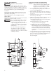
1. Fill sump until primary pump turns on. Mark this
level as “Normal High Water”.
2. When installing the pump, mount the centerline of
the tee inlet at least 2 inches above the normal high
water level.
3. Check that the location of the tee is at least 2 inches
below the top of the sump.
4. Make sure the installation will not interfere with the
primary sump pump operation as follows:
(A) Back up pump must not interfere with primary
pump float switch swing.
(B) Normal high water level must not be high
enough to start the back-up pump.
(C) Install a check valve in the main sump pump
discharge pipe below the back-up pump tee.
Flow in this pipe must be away from the primary
pump. DO NOT INSTALL IT BACKWARDS!
This valve will prevent flow from the back-up
pump back to the sump during battery powered
operation.
5. Cut rigid discharge pipe from primary sump pump
to length, use PVC piping. Tee supplied is 1½" slip
fit; if necessary use 1¼" bushings supplied. Do not
glue the tee until all parts have been trial
fitted and aligned.
WARNING
CAUTION
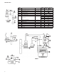
FIGURE 1
Standard Installation
C
L
pump
PUMP
PUMP
PRIMARY
DISCHARGE
PIPE
CHECK
VALV E
CHECK
VALV E
ELBOW
TEE
3
12
11
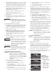
FIGURE 2
Assembly Details
TEE
SW
FLOAT
SW
BACK UP
PUMP
1½
MAX.
1½
MAX.
*PRIMARY
PUMP
SUMP
CHECK VALVE
Must be
installed
to prevent
recirculation
into sump.
“ON”
POSITION
(Primary pump
normal high
water level)
TOP OF SUMP
2" MIN.
2" MIN.
1.6 REF.