
Manual


5
E. Connect the black pump wire to the Negative
battery terminal.
F. Connect the gray switch wire marked + to the
Positive battery terminal.
2. Plug in power cord to a 115-125 Volt AC outlet
delivering at least 2 amps. Do not use a switch
controlled outlet. Mark circuit in main power panel
“Backup sump pump power supply; do not turn off ”.
3. With charger properly connected and plugged in, the
panel on the front of the charger will appear as in
one of the following:
A. If battery is dead, charger will supply about
10 amps power (see Figure 3A).
B. If battery is near full charge, charger will deliver
about 5 amps power (see figure 3B).
C. If battery is fully charged, charging current will
be 0 amps and green LED lamp will be lighted
(see figure 3C).
4. The charger is equipped with a self-resetting circuit
breaker which protects it from temporary overloads.
In case of an overload, the circuit breaker will open.
It automatically resets after a short cool-down
period. In some conditions where the overload is
extended the breaker will cycle, repeating the open/
reset process indefinitely. When this happens,
normally the charger will emit a clicking sound as
the breaker opens and resets.
NOTICE: If the clicking sound continues for more
than 30 minutes or so, check for reversed
charger connections to the battery and for
shorted cells in the battery.
BATTERY MAINTENANCE
NOTICE: To protect battery case from chipping and
gouging, do not let battery sit on concrete
floor (plywood, 2x4’s, etc.). Always install
battery in a dry location that is protected
from flooding.
1. Unplug battery charger.
2. On batteries with removable top caps, measure
specific gravity of electrolyte. Use a hydrometer
(available at auto parts stores). If the specific gravity
of any cell is less than 1.225 or if there is more than
.050 variation between cells, replace the battery.
3. Check electrolyte level and refill as needed.
4. Check battery terminals and clamps for tightness and
corrosion. Clean and tighten as needed.
5. Plug in battery charger.
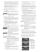
6. Thread check valve tightly into the elbow provided
and plug the pump discharge into the other end of
the elbow. Secure with hose clamp. Slip the plain end
of the check valve into the side socket of the tee.
7. Install the float switch on the stainless steel bracket
provided and attach the bracket as shown.
Adjust bracket to support pump/switch assembly to
approximately level position.
8. Check for clearance to all working parts of the
primary and back-up pump systems.
9. Remove pump assembly from tee. Remove tee
from pump.
10. Using PVC cement, permanently install the tee on
the discharge pipe, according to the PVC cement
instructions.
Hazardous Fumes. Follow cement
manufacturer’s instructions. Use PVC
cement only in a well ventilated area
away from fire or flame.
11. Reinstall switch/bracket assembly.
12. Using PVC cement, permanently install the pump
assembly by cementing the check valve in the tee side
socket, with the pump base approximately level.
13. Adjust the switch/bracket assembly to support the
pump. Tighten the clamp.
14. Make sure battery is fully charged: then check
operation by disconnecting power to the primary
sump pump and filling sump until the battery
operated pump starts. Run pump through one
complete cycle.
15. Operation may be checked at any time by rotating
the float switch knob or ribbed wheel (4) pivots to
turn on the pump.
The liquid sound you hear in the float
portion of the switch is mercury, not
water, and should be disposed of prop-
erly. If you cannot arrange for proper
disposal, the product may be returned
for disposal to place of purchase.
ELECTRICAL CONNECTIONS
Hazardous Voltage. Can cause serious
or fatal electrical shock. Review safety
instructions before operating charger.
Do not modify cord or plug.
CHARGER/BATTERY INSTALLATION
NOTICE: Alarm will sound when charger is first
connected to battery. Press ALARM TEST/
RESET button on charger. If alarm continues
to sound, disconnect one charger lead from
the battery and reconnect it. Press ALARM
TEST/RESET again; alarm will stop
sounding.
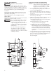
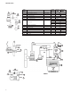
1. Connect charger as shown in Figure 3.
A. Connect Positive (+) lead from charger to
positive battery terminal.
B. Connect (–) lead from charger to negative
battery terminal.
C. Connect the third (blue) lead from the charger to
the blue tap on the brown pump wire just before
the fuse holder.
D. Put the 15 Amp fuse into ½ of the fuse holder
and connect the second half of the fuse holder.
WARNING
CAUTION
WARNING
FIGURE 3 –
Battery Backup
Control Panel
A. Battery depleted –
charging current
10 Amps.
B. Battery nearly
charged – current
about 5 Amps.
C. Charge complete –
current 0 amps,
LED lights up.
3A.
3B.
3C.