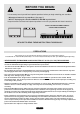
INSTRUcTIONS INSTRUcTIONS INSTRUccIONES ИНСТРУКЦИЯ 7912B UNIVERSAL SOUNDBAR MOUNT SUppORT DE BARRE DE SON UNIVERSEL SOpORTE UNIVERSAL pARA BARRA DE SONIDO УНИВЕРСАЛЬНЫЙ ДЕРЖАТЕЛЬ ЗВУКОВОЙ ПАНЕЛИ Patent pending / Brevet en instance / Patent pendiente / Заявка на патент подана Made in China / Fabriqué en Chine / Hecho en China / Сделано в Китае Do not discard these instructions / Ne pas jeter ces instructions Conserve estas instrucciones / Не выбрасывайте эту инструкцию 040913v1T
This page intentionally left blank
pARTS LIST ENGLISH SB-MP Plastic Plate X2 A1 Horizontal Support Plate X1 SB-SP Metal Support Plate X2 A2 Vertical Metal Exterior Bars X2 A5 Square Adapters X2 A3 Vertical Plastic Interior Bars X2 SB-SC M10 Hollow Hex Bolt X2 A4 Extensions X2 AN M4 Nut X10 N M5 Nut X6 AB M4 x 3/8" (10 mm) X6 JN M6 Nut X8 II M5 x 1" (26 mm) X2 SB-A SB-GL M4 x 7/8" (22 mm) M4 x 1-1/8" (28 mm) X4 X4 SB-SCN M10 Nut X2 AF M8 Nut X6 I M5 x 1-3/16" (30 mm) X2 SB-J M6 x 1" (25 mm) X4 J M6 x 1/2" (12 mm) X8 For u
BEFORE yOU BEGIN: It is necessary to ask yourself two important questions before you begin attaching your soundbar: • What type of mount is my soundbar? (See page 5) • Will I be displaying the soundbar ABOVE or BELOW my television? Keep the answers to these two important questions in mind as you proceed with these instructions.
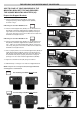
pART 1: pREpARING TO MOUNT THE SOUNDBAR Determine how your soundbar is mounted There are three typical types speaker mounting methods for Soundbars: • kEyHOLE (Fig. 1): This is a slot with a larger circle at the bottom SEE PAGES 6-7 FOR THIS TYPE OF INSTALLATION Fig. 1 • ScREW (Fig. 2): This is commonly found on center channel speakers. There is a threaded nut in the back of the speaker to screw into. SEE PAGES 6-7 FOR THIS TYPE OF INSTALLATION Fig. 2 • BRAckET (Fig.
FOR kEyHOLE AND ScREW MOUNT SOUNDBARS: SKIP TO PAGE 8 IF YOUR SOUNDBAR IS THE MOUNTING BRACKET TYPE AND REQUIRES THE SQUARE MOUNTING ADAPTERS (A5). SB-Sc prepare the Support Brackets: 1-1. Place the M10 Hollow Hex Bolt (SB-SC) into the large hexagonal opening in Plastic Support Bracket (SB-MP) as shown in Fig. 5. SB-Mp Fig. 5 If Mounting the Soundbar ABOVE the TV: 1-2. Place the Metal Support Plate (SB-SP) over the M10 Hollow Hex Bolt (SB-SC) and Plastic Support Bracket (SB-MP) as shown in Fig. 6.
Fig. 10 For keyhole Mounting: SB-Sp SB-Mp 1-6. Insert the Long 1" (26 mm) Screw (II) through the center of the Large Hex Bolt (SB-SC) as shown in Fig. 10 (A longer 1-3/16" (30 mm) Screw (I) has been included if you require a longer length). Allow about 1/4" (6 mm) of space between the head of the screw and the Metal Support Plate (SB-SP) to fit the soundbar's keyhole. I or II SB-Sc 1-7.
FOR BRAckET MOUNTED SOUNDBARS: Fig. 15 Fig. 16 SB-Sc AN SB-Mp SB-Mp ORIENTATION: A5 Fig. 17 NOTE that the slots in the Square Adapters (A5) are different lengths. You will need to find the slot that BEST fits the mounting brackets that came with your soundbar. AA 1-1. Place the M10 Hollow Hex Bolt (SB-SC) into the large hexagonal opening in Plastic Support Bracket (SB-MP) as shown in Fig. 15. 1-2. Insert three small M4 Nuts (AN) into the cavities in Plastic Support Bracket (SB-MP) as shown in Fig.
pART 2: INSTALLING THE VERTIcAL TELEVISION BARS 2-1. With the help of an assistant, and taking extreme caution not to damage the front of your television, lay the TV face-down on a flat, level, and very soft surface. You may want to use soft blankets or towels to cushion the face of the TV. Make sure the outer frame of the television is supported, and that no pressure is applied to the screen of the TV. Fig. 20 A3 2-2. Locate the mounting holes on the back of your TV.
FOR LARGE SIZE TELEVISIONS: 3 Fig. 24 If your television is very large, you may need to extend the Vertical Metal Exterior Bars (A2) quite a distance from the mounting holes in your TV. 2-6. Extend the Vertical Metal Exterior Bars (A2) as far as you need to in order to accomodate your soundbar and TV, however MAkE SURE you leave at least two holes past the TV mounting screw as shown in Fig. 24. This will allow enough support to safely hold your soundbar in place.
pART 3: INSTALLING THE SOUNDBAR 3-1. Attach the Horizontal Support Plate (A1) to the protruding screws of the Vertical Metal Exterior Bars (A2) and secure using two M8 Washers (SB) and two M8 Nuts (AF). Make sure it is even and parallel with the frame of the TV, then tighten fully. (Figs. 27 & 28). Fig. 27 3-2. With the help of an assistant to hold the soundbar in place, attach the soundbar to the Universal Soundbar Mount as you did in Part 1.
NOMENcLATURE DES pIÈcES FRANçAIS SB-MP Plaque en plastique X2 A1 Plaque support horizontale X1 SB-SP Plaque support métallique X2 A2 Barres extérieures verticales métalliques X2 A5 Adaptateurs carrés X2 A3 Barres intérieures verticales en plastique X2 SB-SC Boulon hexagonal taraudé M10 X2 A4 Rallonges X2 AN Écrou M4 X10 N Écrou M5 X6 AB M4 x 3/8" (10 mm) X6 JN Écrou M6 X8 II M5 x 1" (26 mm) X2 SB-A SB-GL M4 x 7/8" (22 mm) M4 x 1-1/8" (28 mm) X4 X4 SB-SCN Écrou M10 X2 AF Écrou M8 X6 I M5 x 1
AVANT DE cOMMENcER : Avant de procéder à la pose de la barre de son, les deux questions importantes suivantes doivent être posées : • Quelle est la méthode de fixation de la barre de son ? (Voir page 14) • La barre de son doit-elle être placée AU-DESSUS ou AU-DESSOUS du téléviseur ? Garder les réponses à ces importantes questions à l'esprit lors de l'exécution de ces instructions.
pARTIE 1 : pRÉpARER LE MONTAGE DE LA BARRE DE SON Déterminer comment la barre de son doit être montée Il y a trois méthodes types de montage des barres de son : • TROU EN pOIRE (Fig. 1) : C'est un trou oblong avec un circle plus grand à la base VOIR CE TYPE DE POSE AUX PAGES 15 ET 16 Fig. 1 • VIS (Fig. 2): Cette méthode est courante sur les enceintes centrales. Il y a un écrou taraudé au dos de l'enceinte pour le vissage du support. VOIR CE TYPE DE POSE AUX PAGES 15 ET 16 Fig.
BARRES DE SON À FIxATION pAR TROUS EN pOIRE ET VIS : PASSER À LA PAGE 17 SI LA BARRE DE SON EST DE TYPE À ÉTRIER DE FIXATION ET NÉCESSITE LES ADAPTATEURS DE MONTAGE CARRÉS (A5). SB-Sc préparer les supports de fixation : 1-1. Placer le boulon hexagonal taraudé M10 (SB-SC) dans la grande ouverture hexagonale de la plaque en plastique (SB-MP) comme sur la Fig. 5. Pose de la barre de son AU-DESSUS du téléviseur : 1-2.
Fixation par des trous en poire : 1-6. Enfiler la longue vis de 26 mm (II) dans le centre du boulon hexagonal taraudé (SB-SC) comme sur la Fig.10 (une vis plus longue, de 30 mm, (I) a été fournie si un plus grande longueur est requise). Prévoir un espace d'environ 6 mm (1/4 po) entre la tête de la vis et la plaque support métallique (SB-SP) pour le passage du trou en poire de la barre de son. 1-7.
BARRES DE SON À ÉTRIERS DE FIxATION : Fig. 15 Fig. 16 SB-Sc AN SB-Mp SB-Mp ORIENTATION : A5 Fig. 17 REMARQUEZ que les trous oblongs dans les adaptateurs carrés (A5) sont de longueurs différentes. Veiller à trouver le trou oblong qui convient le MIEUX aux étriers de fixation fournis avec la barre de son. AA 1-1. Placer le boulon hexagonal taraudé M10 (SB-SC) dans la grande ouverture hexagonale de la plaque en plastique (SB-MP) comme sur la Fig. 15. 1-2.
pARTIE 2 : pOSE DES BARRES VERTIcALES DE TÉLÉVISEUR 2-1. Avec l'aide d'une autre personne et en faisant preuve de précaution extrême pour ne pas endommager l'écran du téléviseur, poser le téléviseur à plat sur sa face avant sur une surface plane, horizontale et très douce. Utiliser éventuellement des couvertures ou des serviettes pour protéger la face avant du téléviseur. S'assurer que le téléviseur est en appui sur son cadre extérieur et qu'aucune pression n'est exercée sur son écran. Fig. 20 A3 2-2.
TÉLÉVISEURS DE GRAND FORMAT : 3 Fig. 24 Si le téléviseur est de très grand format, il peut être nécessaire de faire dépasser les barres extérieures verticales métalliques (A2) d'une longueur relativement importante depuis les trous de fixation du téléviseur. 1 2-6. Faire dépasser les barres extérieures verticales métalliques (A2) autant que nécessaire pour le placement de la barre de son.
pARTIE 3 : pOSE DE LA BARRE DE SON 3-1. Attacher la plaque support horizontale (A1) aux vis saillantes des barres extérieures verticales métalliques (A2) et fixer avec deux rondelles M8 (SB) et deux écrous M8 (AF). Vérifier qu'elle est horizontale et parallèle au cadre du téléviseur, puis serrer à fond (Fig. 27 et 28). Fig. 27 3-2. Avec l'aide d'une autre personne pour tenir la barre de son en place, attacher la barre de son au support de barre de son universel comme cela a été fait à la Partie 1.
LISTA DE pIEZAS ESpAñOL SB-MP Placa de plástico X2 A1 Placa de soporte horizontal X1 SB-SP Placa metálica de soporte X2 A2 Barras metálicas externas verticales X2 A5 Adaptadores cuadrados X2 A3 Barras de plástico internas verticales X2 SB-SC Tornillo hexagonal hueco M10 X2 A4 Extensiones X2 AN N Tuerca M4 Tuerca M5 X10 X6 AB M4 x 3/8" (10 mm) X6 JN Tuerca M6 X8 II M5 x 1" (26 mm) X2 SB-A SB-GL M4 x 7/8" (22 mm) M4 x 1-1/8" (28 mm) X4 X4 SB-SCN Tuerca M10 X2 AF Tuerca M8 X6 I M5 x 1-3/16" (30
ANTES DE cOMENZAR: Es necesario que se haga dos preguntas importantes antes de comenzar a colocar la barra de sonido: • ¿Qué tipo de soporte tiene mi barra de sonido? (Ver página 23) • ¿colocaré la barra SOBRE o BAJO mi televisor? Recuerde las respuestas a estas dos importantes preguntas mientras continúa con estas instrucciones.
pARTE 1: pREpARAcIÓN pARA MONTAR LA BARRA DE SONIDO Determine cómo se monta su barra de sonido Hay tres métodos de montaje típicos para los altavoces de las barras de sonido: • OJO DE LLAVE (Fig. 1): Es una ranura con un círculo más grande en la parte inferior VER PÁGINAS 24-25 PARA ESTE TIPO DE INSTALACIÓN Fig. 1 • TORNILLO (Fig. 2): Suele encontrarse en los altavoces de canal central. La parte trasera del altavoz tiene una tuerca roscada para atornillar.
pARA LAS BARRAS DE SONIDO cON SOpORTE DE OJO DE LLAVE y TORNILLO: VAYA A LA PÁGINA 26 SI SU BARRA DE SONIDO SE MONTA CON SOPORTES Y REQUIERE LOS ADAPTADORES CUADRADOS (A5). SB-Sc preparación de los soportes de apoyo: 1-1. Coloque el tornillo hexagonal hueco M10 (SB-SC) en la abertura hexagonal grande del soporte de plástico de apoyo (SB-MP) tal como se muestra en la Fig. 5. Si va a colocar la barra de sonido SOBRE el TV 1-2.
Fig. 10 para el montaje con ojo de llave: 1-6. Inserte el tornillo largo de 1" (26 mm) (II) por el centro del tornillo hexagonal grande (SB-SC) como se ve en la Fig. 10, (Si necesita más longitud, se incluyó un tornillo de 1-3/16" (30 mm) (I)). Deje aproximadamente 1/4'' (6 mm) de espacio entre la cabeza del tornillo y la placa metálica de soporte (SB-SP) para acomodar el ojo de llave de la barra de sonido. 1-7.
pARA BARRAS DE SONIDO cON SOpORTES DE ApOyO: Fig. 15 Fig. 16 SB-Sc AN SB-Mp SB-Mp ORIENTAcIÓN: A5 Fig. 17 NOTE que las ranuras de los adaptadores cuadrados (A5) tienen distintas longitudes. Deberá encontrar la ranura que MEJOR se adapte a los soportes de montaje que vienen con su barra de sonido. AA 1-1. Coloque el tornillo hexagonal hueco M10 (SB-SC) en la abertura hexagonal grande del soporte de plástico de apoyo (SB-MP) tal como se muestra en la Fig. 15. 1-2.
pARTE 2: INSTALAcIÓN DE LAS BARRAS VERTIcALES pARA TELEVISOR Fig. 20 2-1. Con un ayudante y con extrema precaución para no dañar el frente de su televisor, apóyelo boca abajo sobre una superficie plana, nivelada y muy suave. Puede utilizar unas mantas o toallas suaves para proteger el frente del televisor. Asegúrese de que el marco externo del televisor esté apoyado y que no se aplique presión a la pantalla. A3 2-2. Ubique los orificios de montaje en la parte trasera de su TV.
pARA TELEVISORES GRANDES: 3 Fig. 24 Si su televisor es muy grande, puede necesitar extender un poco la distancia de las barras metálicas externas verticales (A2) de los orificios de montaje del TV. 2-6. Extienda las barras metálicas externas verticales (A2) tanto como sea necesario para acomodar su barra de sonido y el TV, sin embargo, ASEGÚRESE de dejar al menos dos orificios después del tornillo de montaje del TV, tal como se ve en la Fig. 24.
pARTE 3: INSTALAcIÓN DE LA BARRA DE SONIDO 3-1. Fije la placa de soporte horizontal (A1) a los tornillos sobresalientes de las barras metálicas externas verticales (A2) y asegúrela con dos arandelas M8 (SB) y dos tuercas M8 (AF). Asegúrese de que todo esté uniforme y paralelo al marco del televisor al apretarlas por completo. (Figs. 27 y 28). Fig. 27 3-2.
ПЕРЕЧЕНЬ ДЕТАЛЕЙ РУССКИЙ SB-MP Пластмассовая пластина X2 A1 Горизонтальная опорная пластина X1 SB-SP Металлическая опорная пластина X2 A2 Вертикальные металлические внешние планки X2 A5 Адаптеры X2 A3 Вертикальные пластмассовые внутренние планки X2 SB-SC Полый болт М10 с гексагональной головкой X2 A4 Удлинители X2 AN Гайка М4 X10 N Гайка М5 X6 AB M4 x 3/8" (10 mm) X6 JN Гайка М6 X8 II M5 x 1" (26 mm) X2 SB-A SB-GL M4 x 7/8" (22 mm) M4 x 1-1/8" (28 mm) X4 X4 SB-SCN Гайка М10 X2 AF Гайка М8 X6
ПЕРЕД ТЕМ КАК УСТАНАВЛИВАТЬ: Перед тем как начать устанавливать звуковую панель, необходимо задать себе и ответить на два вопроса: • На какой тип установки рассчитана моя звуковая панель? (См. страницу 32) • Куда я буду устанавливать звуковую панель – НАД телевизором или ПОД ним? Вы всегда должны помнить ответы на эти два важных вопроса, когда вы будете следовать указаниям этой инструкции.
ЧАСТЬ 1. ПОДГОТОВКА К УСТАНОВКЕ ЗВУКОВОЙ ПАНЕЛИ Определите, как устанавливается ваша звуковая панель Для звуковых панелей используются три типа установки динамиков: • «ЗАМОЧНАЯ СКВАЖИНА» (Рис. 1) Представляет собой прорезь с круглым отверстием внизу, диаметр которого больше ширины прорези ЭТОТ ТИП УСТАНОВКИ ОПИСАН НА СТРАНИЦАХ 33-34 Рис. 1 • «ВИНТ» (Рис.2) Обычно используется в динамиках центрального канала. На задней стенке динамика имеется резьбовая гайка для ввинчивания.
ДЛЯ ЗВУКОВЫХ ПАНЕЛЕЙ С ТИПАМИ УСТАНОВКИ «ЗАМОЧНАЯ СКВАЖИНА» И «ВИНТ» ПЕРЕЙТИ К СТРАНИЦЕ 35, ЕСЛИ ВАША ЗВУКОВАЯ ПАНЕЛЬ С ТИПОМ УСТАНОВКИ «КРОНШТЕЙН» И ТРЕБУЕТ ИСПОЛЬЗОВАНИЯ КВАДРАТНЫХ УСТАНОВОЧНЫХ АДАПТЕРОВ (А5). SB-Sc Подготовьте опорные кронштейны 1-1. Вставьте полый болт М10 с гексагональной головкой (SB-SC) в большой гексагональный выступ с отверстием на пластмассовой опорной пластине (SB-MP), как показано на Рис. 5. Если звуковая панель устанавливается НАД телевизором: 1-2.
Для установки типа Рис. 10 “замочная скважина”: 1-6. Вставьте длинный 26-мм винт (II) через центр большого болта с гексагональной головкой (SB-SC), как показано на Рис. 10 (более длинный 30-мм винт (I) включен в комплект для тех случаев, когда длины 26-мм винта недостаточно). Между головкой винта и металлической опорной пластиной (SB-SP) должен быть зазор ¼ дюйма (6 мм), чтобы соответствовать размеру «замочной скважины» звуковой панели. 1-7.
ДЛЯ ЗВУКОВЫХ ПАНЕЛЕЙ С ТИПОМ УСТАНОВКИ «КРОНШТЕЙН» Рис. 15 Рис. 16 SB-Sc AN SB-Mp SB-Mp ОБРАТИТЕ ВНИМАНИЕ: Прорези на квадратных адаптерах (А5) отличаются по длине. Вам нужно будет найти прорезь, которая ЛУЧШЕ ВСЕГО подходит к установочным кронштейнам, полученным в комплекте с вашей звуковой панелью. A5 Рис. 17 AA 1-1. Вставьте полый болт М10 с гексагональной головкой (SB-SC) в большой гексагональный выступ с отверстием на пластмассовой опорной пластине (SB-MP), как показано на Рис. 15. 1-2.
ЧАСТЬ 2. УСТАНОВКА ВЕРТИКАЛЬНЫХ ТЕЛЕВИЗОРНЫХ ПЛАНОК 2-1. Вместе с помощником, соблюдая все меры предосторожности, чтобы не повредить переднюю часть телевизора, осторожно положите телевизор экраном вниз на плоскую горизонтальную и очень мягкую поверхность. Для защиты экрана телевизора можно использовать мягкие одеяла или полотенца. Убедитесь, что рама корпуса телевизора поддерживается и что нет никакого давления на экран телевизора. Рис. 20 A3 2-2.
ДЛЯ ТЕЛЕВИЗОРОВ БОЛЬШОГО РАЗМЕРА: 3 Рис. 24 Если у вас очень большой телевизор, то может потребоваться выдвинуть вертикальные металлические внешние планки (А2) на порядочное расстояние от крепежных отверстий на телевизоре. 1 2-6.
ЧАСТЬ 3. УСТАНОВКА ЗВУКОВОЙ ПАНЕЛИ 3-1. Прикрепите горизонтальную опорную пластину (А1) к выступающим винтам вертикальных металлических внешних планок (А2) и закрепите, используя две шайбы М8 (SB) и две гайки М8 (AF). Убедитесь, что пластина установлена правильно и параллельно корпусу телевизора; полностью затяните (Рис. 27 и 28). Рис. 27 3-2.