Bell System (Telephones) Ltd.
bellissimo 2-72 Way Video Entry System PD-098 Issue 3C Installation and Operating Manual Page 2 of 40
bellissimo 2-72 Way Video Entry System TABLE OF CONTENTS TABLE OF CONTENTS ......................................................................................................3 INTRODUCTION .................................................................................................................4 DESCRIPTION .....................................................................................................................4 MAIN FEATURES ............................................................
bellissimo 2-72 Way Video Entry System Introduction Description A bellissimo video door entry system consists of a door panel, positioned at the entrance of a building, video telephones (videophone), placed inside of the building for the convenience of the occupants and a power supply and controller which are usually located inside an electrical cupboard. The door panel comprises of a two-way speech unit, a camera and several push buttons – one of which must be depressed by a visitor to initiate a call.
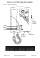
bellissimo 2-72 Way Video Entry System bellissimo Colour Videophone Display Angle View Mute Lock Ringer Volume Button View / camera select Mute on/off Lock PD-098 Issue 3C Lamp Amber Red Green Steady Call in progress Videophone is muted Door is open Contrast Flashing Ringing Videophone is off-hook Press to release lock Installation and Operating Manual Page 5 of 40
bellissimo 2-72 Way Video Entry System Basic System Operation Call sequence When the call button is pressed at the entrance panel it causes the videophone to ring and the amber view lamp to flash. The videophone will continue to ring for up to 30 seconds or until the resident responds by picking up the handset. At this time the resident can freely converse with the visitor whose image is now displayed on the videophone; at the same time the green lock lamp will flash to highlight the lock button.
bellissimo 2-72 Way Video Entry System Door Status Indication The green lock lamp on the videophone will illuminate to warn the resident that a door has been left open following a call. This feature requires a door monitor contact to be fitted. Call Privacy Once a call has been made from an entrance panel only the videophone(s) which is/are ringing may answer the call.
bellissimo 2-72 Way Video Entry System DDA Functionality The bellissimo video system has a range of options for entrance panels to help meet the requirements of the Disability Discrimination Act (DDA), including Illuminated Tactile buttons, reassurance tones and LED indicators for “Speak Now” and “Door Open”. Contact your sales representative for further details. Reassurance tone setting is on page 19.
bellissimo 2-72 Way Video Entry System Design Considerations Equipment List A BS-n bellissimo Video Kit (where n is the no of ways) comprises the following: Model No N x BS 1 x BSPn 1 x BSD8 or BSD72 M x BSC4 K x PS4 1 x 203 Description Videophone (N is the no of phones) Standard panel with a speech unit and camera. Door controller (BSD72 required for > 8 ways) Video controller (one required for every 4 ways = N/4 rounded up) 4A 12V power supply.
bellissimo 2-72 Way Video Entry System Entrance Panel – Important Note Careful consideration should be given to the location of the entrance panel to ensure the best possible lighting conditions for the camera. In general strong back lighting of the subject (by the sun and sky) should be avoided, as the contrast between foreground and background may be too great for the camera. The field of view should contain as little of the sky as possible, particularly if south facing.
bellissimo 2-72 Way Video Entry System Exact power supply requirements depend upon many factors. The number of power supplies included within a standard ‘kit’ or quotation assumes that all controllers are installed in one location and that there are no extensions. The following table gives examples of the minimum number of controllers and power supplies for a given number of entrance doors and flats.
bellissimo 2-72 Way Video Entry System Cable Specification All system wiring must be carried out using Cat5 signal cable and where necessary 1mm² (or greater) power cable as tabulated below. Cat5 cable has a known performance for the transmission of video signals, whilst telephone or alarm cables are not suitable. Bell System will be unable to offer any warranty or support for systems installed using incorrect cables.
bellissimo 2-72 Way Video Entry System Cable Distances – Version 2 Colour Videophones Video Controller to Videophone Distance Cable Comments < 150m 1 x Cat5 > 300m 1 x Cat5 2 x 1mm2 Single videophone + 3 < 50m 1 x Cat5 Only Master videophone has extensions on each output, < 200m ‘Auto display’; 1 x Cat5 all cable powered extensions are daisy-chained 2 x 1mm2 Single videophone per < 150m 1 x Cat5 150m maximum to the cable output with separately powered videophone; > 300m 1 x Cat5 2 powered extensions daisy-c
bellissimo 2-72 Way Video Entry System Installation & Commissioning Checklist The following checklist is a summary of what is required. Refer to the relevant pages for further details. ● Review the section headed ‘Safety Information’ on page 39. ● Ensure that ‘Design Considerations’ on page 9 have been understood. ● Confirm that Cat5 cable has been specified. ● Install the system according to instructions in this section. ● Check/set the door controller jumper and switch settings.
bellissimo 2-72 Way Video Entry System Audio Phones The BSA audio phone can be used as a lower cost alternative to an extension videophone. It is styled like the bellissimo videophone. The phone is manufactured in white and grey high-impact ABS plastic that imparts high durability and compliments most wall furnishings. It incorporates both mute and lock illuminated buttons and it has an Electronic Ringing Tone with rotary preset volume.
bellissimo 2-72 Way Video Entry System tend to require at least 1.5A peak current and this will require the use of an isolation relay and a separate power supply for the lock. Exit Button Input The exit button is used to unlock the door for the preset lock operating time. The input is designed only for use with a normally open push button. ‘Exit +’ is the input and ‘Exit –’ is internally connected to 0V.
bellissimo 2-72 Way Video Entry System BSD8/72 Door Controller Switch Settings Talking Time/Videophone Active DIP SW1 (1-4) Talk Time 15s 20s 30s 45s 60s 75s 90s 120s 150s 180s 60s 60s* SW1 SW2 SW3 (ASDFGHJK) (ASDFGHJK) (QWERGHJK) 4 3 2 1 On On On On On On On Off On On Off On On On Off Off On Off On On On Off On Off On Off Off On On Off Off Off Off On On On Off On On Off Other settings Off Off Off Off OFF ↔ ON *Default setting Ringing Time/Call Time and Ring Effect DIP SW1 (5-8) 7 On On On On Off Off O
bellissimo 2-72 Way Video Entry System Lock Operate Time Dip SW2 (1-3) 2 On On Off Off On On Off Off 1 On Off On Off On Off On Off Lock Time 3s* 4s 5s 6s 8s 10s 15s 20s SW1 SW2 SW3 (ASDFGHJK) (123FGHJK) (ASDFGHJK) 3 On On On On Off Off Off Off OFF ↔ ON *Default setting Individual Functions DIP SW2 (4-8) SW1 SW2 SW3 (ASDFGHJK) (ASDRTYUI) (ASDFGHJK) OFF ↔ ON SW2-4 Lock Type *Off Fail secure lock On Fail safe lock SW2-5 Door Status Switch *Off Contacts Open when Door is Closed On Contacts Closed when
bellissimo 2-72 Way Video Entry System Camera Numbering DIP SW3 (1-8) SW1 SW2 SW3 (12345678) (ASDFGHJK) (ASDFGHJK) Camera 1 at this door Last Camera 4 3 2 1 Number 8 7 6 5 Number On On On On *1 On On On On *1 On On On Off 2 On On On Off 2 On On Off On 3 agama On On Off On 3 On On Off Off 4 On On Off Off 4 On Off On On 5 On Off On On 5 On Off On Off 6 On Off On Off 6 On Off Off On 7 On Off Off On 7 On Off Off Off 8 On Off Off Off 8 Off On On On 9 Off On On On 9 Off On On Off 10 Off On On Off 10 Off On Off
bellissimo 2-72 Way Video Entry System BSC4 Video Controller Settings Jumper settings The “Video Gain” jumper on video controllers should always be set to “0” unless directed by Bell System Technical. This jumper is only required on some systems with very long camera to videophone cable runs well in excess of 150m. Inappropriate use of this jumper with short runs will cause picture problems.
bellissimo 2-72 Way Video Entry System Address Offset SW7 – Build 7 onwards SW7 is an 8 bit switch that is used to increase the addressing range. For each bit that is switched ON add the corresponding value to the amount set by SW6. This allows flat addresses up to 3210 to be set (6410 or higher with the jumper below). Offset +1 +2 +50 +100 +200 +400 +800 +1600 SW7 Each bit on SW7 adds the corresponding amount to the address set by SW6.
bellissimo 2-72 Way Video Entry System BS Videophone Switch Settings Mute Time Setting SW2 (1-4) 3 On On On On Off Off Off Off On On On On Off Off Off Off 2 On On Off Off On On Off Off On On Off Off On On Off Off 1 On Off On Off On Off On Off On Off On Off On Off On Off SW2 Mute Time Disabled¹ 2 minutes 5 minutes 10 minutes 15 minutes 20 minutes 30 minutes 45 minutes 1 hour 2 hours 4 hours 5 hours 6 hours 8 hours 10 hours *Indefinite² (QWERGHJK) 4 On On On On On On On On Off Off Off Off Off Off Off Of
bellissimo 2-72 Way Video Entry System Troubleshooting Common Faults A very high percentage of calls to our technical support number, regarding new installations, are resolved to faulty wiring. The reasons for these are various: Broken cores, especially short links, sometimes broken inside the insulation! Connectors clamped onto the insulation instead of copper. Wire in the wrong side of a rising clamp connection, the clamps need to be unscrewed far enough to stop the wire going “underneath”.
bellissimo 2-72 Way Video Entry System Lock Release Problems Lock release does not operate or clicks but does not open. Maglock does not hold strongly. TEST: Press ‘Test’ Button on Door Controller (when system idle): Lock release operates all the time or in reverse. Lock operates from the exit button but not the test button or phone. Connections to Lock Release are open or shorted. Voltage drop due to cable too thin. Lock current is too high; Power supply is resetting.
bellissimo 2-72 Way Video Entry System Speech Problems Loud tone at the entrance speaker. (Acoustic feedback) Low volume speech in one or both directions No speech from videophone to entrance No speech from entrance to videophone PD-098 Issue 3C Volume controls set too high Broken Audio 1 or 2 wire in the cabling. Intermittent or broken wire in Data A or B. Videophone has reset; see the power faults table.
bellissimo 2-72 Way Video Entry System Specifications BSD8/72 Door controller Size BSD8: 185mm x 230mm x 42mm BSD72: 360mm x 240mm x 40mm 10.8V min, 13.8V typical, 15V max 80mA idle @13.8V, 250mA active includes speech not cameras Supply Voltage Current Consumption Model C-CAMBS Colour Camera Size Supply Voltage Current consumption Image Device Sensitivity Minimum Focus Viewing Angle Video Output Resolution Back light compensation 60mm x 57mm x 31mm 10V d.c. minimum, 15V d.c.
bellissimo 2-72 Way Video Entry System PS4 Power Supply Size Output Voltage (regulated) Output Current Mains Supply Internal Fuse Supply Voltage Temperature Range 236mm x 105mm x 81mm 13.5V d.c. min, 13.8V d.c. nom, 14.1V d.c. max 3A continuous, 4A peak (5 minutes max) Not user replaceable 230V 50Hz nominal 0 ºC to 50 ºC 340C Power Supply Size Output Voltage (regulated) Output Current Mains Supply Internal Fuse Supply Voltage Temperature Range 140mm x 60mm x 53mm 13.5V Min, 13.8V Nom, 14.
bellissimo 2-72 Way Video Entry System Diagram A – 2-72 Way Basic System Overview Cabling For maximum distance see text (For extension phones see phone diagrams) 1 Cat5 per phone BSC4 4 way Video Controller BSC4 4 way Video Controller Cat5 Further Controllers 2 x 1mm² Further Entrances PSU PS4 12V Cat5 Cat5 Cat5 BSD8 (2-8 way) BSD72 (9-72 way) Door Controller BSD8 (2-8 way) BSD72 (9-72 way) Door Controller PSU PS4 12V Control equipment Cat5 requirements All cable MUST be 4 pairs standard plus
bellissimo 2-72 Way Video Entry System Diagram B – Large system Overview Illustration of Power Supply Distribution Further Controllers Further Entrances 2 x 1mm² BSC4 Video Controller Passthru Cat5 Input 2 x 1mm² Cat5 BSC4 Video Controller Input Output Passthru BSD8 (2-8 way) BSD72 (9-72 way) Door Controller Door Panel Input Cat5 PSU PS4 12V 2 x 1mm² Cat5 Input Output BSC4 Video Controller BSD8 (2-8 way) BSD72 (9-72 way) Door Controller PSU PS4 12V Passthru Input 2 x 1mm² Cat5 Cat5 Inp
bellissimo 2-72 Way Video Entry System Diagram C – BSD8 PCB Detail The 72 way Expansion PCB not shown It simply has 8 by 8 way terminal blocks For Call Inputs 9 to 72 and is connected by a short ribbon connector Input Output + - M S + - M S - + 2 1 B A - - + 2 1 B A - Camera 1 Camera 2 Video Audio Data Commn Video Audio Data Commn Cam 100 75 High 100 75 High Cam2 SW2 Expansion SW1 43210 Audio Speech Unit C R O T Cam1 Video SW3 Video Gain Label BSD8/72 Version No Build No Test Status 1 bell
bellissimo 2-72 Way Video Entry System Diagram D – 2-72 Way Basic System Wiring Detail PD-098 Issue 3C Installation and Operating Manual Page 31 of 40
bellissimo 2-72 Way Video Entry System Diagram E – 2-72 Way Multiple Entrance Wiring Detail For maximum distance see text (For extension phones see phone diagrams) 1mm² 1mm² 1mm² 1mm² Lock wiring options Lock 0.5A 1.0A 12m 1 pair 1 pair 25m 1 pair 2 pair 50m 2 pair 4 pair 50m 2x1mm² 2x1mm² All signal cable MUST be Cat5 See "Cable Specification" Cat5 4 twisted pairs data cable.
bellissimo 2-72 Way Video Entry System Diagram F – Extension Videophone Wiring See tables in text for maximum cable runs and cable cross sections. Additional power cores can be used for longer runs. Master 1 Cat 5 Plus Power Cores PD-098 Issue 3C Extension Extension Extension Extension videophones MUST be "daisy chain" wired. An extension audio phone may be star wired. Only one videophone must select "auto display".
bellissimo 2-72 Way Video Entry System Diagram G – Videophone Local Power Wiring Where more than one extension phone is required to provide "auto display" then additional power supplies will be required Master Extension Extension Extension 1 Cat5 PSU 340C 12V PD-098 Issue 3C Installation and Operating Manual PSU 340C 12V Page 34 of 40
bellissimo 2-72 Way Video Entry System Diagram H – Option Details Camera Termination Options Cameras may be wired in either twisted pair or coax and shared with other equipment.
bellissimo 2-72 Way Video Entry System Diagram I – 2-72 Way Additional DDA Wiring PD-098 Issue 3C Installation and Operating Manual Page 36 of 40
bellissimo 2-72 Way Video Entry System Diagram J – bellissimo Combined System Connections Connecting a Bellcode Coded Access Controller Connect the lock release as per this manual. Leave the Bellcode controller set to fail secure, the BSD controller sets the lock type. See "Bellcode Manual inc CK200 CS109 (PD-078)" for the other installation and setting instructions. Note 1. A normally open exit button can still be wired to the Bellcode unit in addition to the bellissimo wiring. Note 2.
bellissimo 2-72 Way Video Entry System Diagram K – ACT Proximity to bellissimo Connections ACT 1000/2000/3000 Proximity Controller ACT 100e Proximity Extender Notes 1. Connect the lock release or Maglock using the ACT Manuals. 2. Leave the BSD controller set to Fail Secure regardless of the type of release used. 3. A normally open exit button can still be fitted to the ACT controller in addition to the bellissimo wiring. 4.
bellissimo 2-72 Way Video Entry System Safety Information and Declarations Connections to the 240VAC mains supply must be carried out by a qualified electrician or similar competent person, and made in accordance with current legislative requirements. A two-pole switch (as provided by a Consumer Unit or Switch-Fuse) must be included to isolate both Live and Neutral during Installation or Maintenance.
bellissimo 2-72 Way Video Entry System Bell System (Telephones) Ltd. Presley Way, Crown Hill, Milton Keynes MK8 0ET. Tel: 01908 261106 (Sales and Technical Support) FAX: 01908 261116 OR Local rate numbers Tel: 0845 121 4008 (Sales and Technical Support) FAX: 0845 121 4009 E-mail: sales@bellsystem.co.uk technical@bellsystem.co.uk Website: www.bellsystem.co.uk Standards This product complies with European directive 89/336/EEC on Electromagnetic Compatibility and Low Voltage Directive 72/23/EEC.