
User's Manual

BSX Isolated Audio Entry System
PD-142 Issue 1 Installation and Operating Manual Page 21 of 32
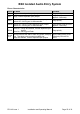
Troubleshooting Lock Release problems
Use this section to diagnose incorrect operation of the lock release when operated from a
phone or the exit button (see basic functional test Pg 27). Perform the additional tests as
described below using the Test button on the PCB controller and diagnose from the table.
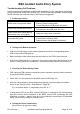
Test1: (Always use this test first to diagnose lock release problems)
Press the TEST button on the Door Controller (when system is idle*).
Confirm ‘LOCK’ LED goes on for 3S (fail secure) or off for 3S (fail safe).
Confirm Lock Release operates for 3S.
Fault
Cause
LOCK does not operate but LED
flashes for 3S.
Faulty/incorrect connections to Lock (open- circuit).
Voltage drop due to cable too thin.
Lock release jammed due to over tight fitting.
Lock clicks but does not open;
LED flashes briefly.
Lock current is too high; PSU is resetting; check
lock release specification (1A max).
Short-circuit on LOCK connections.
Maglock does not hold strongly.
Voltage drop due to insufficient cable diameter.
Lock open/close operation is
reversed.
Check fail safe/fail secure SW1-8 selection matches
the lock type.
Lock operates all the time.
Normally closed switch used for exit button; replace
with normally open switch.
Exit terminals are short-circuit.
Lock operates from the exit button
but not test button or phone.
Normally closed switch has been used for exit
button.
Lock operates from the test
button but not from a phone.
NB Phone must ring and be picked up before
operating the lock button
Faulty connection to phone Z.
Stuck lock button
No Lock Tone at the door.
R core is broken.
Lock Tone Volume turned down on BSX2 PCB.
Phone Speech volume turned down on 61.
No power to 61 speech unit.
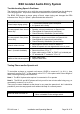
Test2: (Use this test if the lock cannot be made to operate using Test1)
Disconnect LOCK and EXIT by unplugging the terminal block at the controller.
Press TEST button on the Door Controller (when system is idle*).
Confirm ‘LOCK’ LED goes on for 3S (fail secure) or off for 3S (fail safe).
Check Output Voltage at LOCK terminals:
Fail Secure: LOCK voltage 12-14V for 3S returning to 0V
Fail Safe: LOCK Voltage 0V for 3S (Normally 12-14V)
The LED and Output Voltage are
correct under Test2:
Re-check lock connections and cable.
Test lock release on an independent PSU.
LED does not operate.
Power Supply or Controller problems:
Contact Technical support.
No change in output voltage.