Bell System (Telephones) Ltd. BSX DOOR ENTRY TELEPHONE EXCHANGE Installation and Operation Issue 3.00 PLEASE READ THIS MANUAL PRIOR TO INSTALLATION.
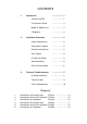
CONTENTS 1. 2. 3. Introduction ...................... 1 Control Unit BSX ...................... 1 The Entrance Panel ...................... 2 Model 51 Speech unit ...................... 2 Telephones ...................... 2 Installation Procedure ...................... 3 Cable Requirements ...................... 3 Connections to panel ...................... 5 Electric Lock Release ...................... 5 Tone Output ...................... 5 Fire Service Switch ......................
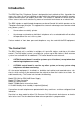
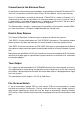
Introduction The BSX Door Entry Telephone System is designed for low rise blocks of flats. It provides the means for visitors to call an individual resident within the building and to establish two-way speech communication (full duplex) with them. The resident is allowed full control over the callers' access to the main entrance by means of an electric lock release or an electric lock. The BSX includes a sophisticated microprocessor-based Control Unit which operates on the 'Telephone Exchange' principle.
The Entrance Panel This is commonly a model VRP or LCP series panel, being a flush mounting stainless steel (BS316) vandal-resistant panel. The panel is fixed by tamper-proof bolts and is to be located on the wall adjacent to the main entrance of the dwellings. The panel can be supplied in a variety of sizes and with custom engraving details. A single flush type vandal resistant button is provided for each flat and one for the timed entry of Services.
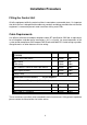
Installation Procedure Fitting the Control Unit All of the equipment within the control unit box is mounted on a removable plate. It is important that while the box is being drilled for cable-entry conduits and being secured to the wall that the equipment is removed to prevent metal swarf from falling onto PCBs. Cable Requirements Use 0.
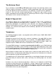
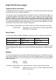
Model PSU138 Power Supply Important Safety Information The Model PSU138 Power Supply must be mounted in a ventilated cabinet/enclosure designed to house 240V AC mains electrical equipment. The cabinet must be in a protected indoor environment, close to a 240V electrical supply, e.g. an electrical cupboard. Connections to the 240V AC mains supply must be carried out by a qualified electrician or similar competent person, and made in accordance with accepted safety practices.
Connections to the Entrance Panel All connections to the entrance panel and doors are provided by the control PCB marked 'CTX'; if the unit is a two door system then there will be 2 of these boards, one for each entrance. Up to 16 push-buttons are wired to the control CTX816 PCB as shown on Diagram 2. It is unnecessary to run a pair of connections for each push-button; by using a system of '2 out of 8 combinations' the number of connections is reduced to a maximum of 8.
Connections to the Telephones The telephone connections are provided by the RELAY PCB in the control unit marked 'RLX'. Each relay board has provision for 8 telephones , hence a 16-way system has two of these boards and a 40-way system has five. There are 6 connections to each 500X telephone and 7 connections for 500LX telephone; a separate cable should be used for each telephone.
Testing & Troubleshooting Push-button Operation Apply mains power to the control unit and turn on at the fused isolator switch. When a push-button is pressed the associated speech-circuit on the relay board (RLX) should engaged for 60 secs then drop-out. Each circuit on the relay board has an led indicator adjacent to the telephone terminal block. Test each button on the entrance panel in turn confirming that the associated LED only comes on, and wait each time for it to clear.
allowing a space between the speech unit and the inside surface of the panel (ie grill). The connections affecting the speech operation are CHROT to the speech unit and R O T to the phone; R carries speech from phone to panel and T from panel to phone with O being the common negative; C & H carry power to the speech unit where C is +12VDC and H is -12VDC ( H & O are connected together internally within the speech unit).
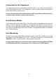
Technical Help If you are experiencing any problems or have any questions regarding the installation please contact the Manufacturers:- Head Office Bell System (Telephones) Ltd Presley Way Crownhill Milton Keynes MK8 0ET Tel: 01908 261106 Fax: 01908 261116 email: techhelp@bellsystem.co.
The TS2000 Time-Clock Module This section describes the operation and programming of the TS2000 Time Clock module for use with the Tradesman’s facility. CAUTION The unit is intended for 12V AC / DC operation only, and must not be connected to the Mains supply or used to switch Mains voltages. Operation N.B. Before programming or setting the clock for the 1st time press the RESET button.
To set the current TIME and DAY: 1. Hold and press until the correct day is displayed. 2. Hold and press until the correct hour is displayed. 3. Hold and press until the correct minutes are displayed. To set the programs: 1. Press once, 1on will appear. This displays the switch on time of the 1st program. 2. Press to select the program period.
Reviewing the programs: Press each time to toggle through the 8 on and off settings. Manual Override Press to toggle through ON/AUTO/OFF modes as indicated by the Timer Status Bar. ON mode turns on the timer. OFF mode turns off the timer. AUTO mode runs the set program. Switching from ON to AUTO will turn ON the timer until the next OFF period. Switching from OFF to AUTO will turn OFF the timer until the next ON period.
13
14
15
16
17
18