
User manual


max.
1Ad.c.
SWC
SCU
O
R
H
I
Z
T
E
U
D
A
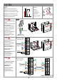
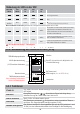
Einbau der Stromversorungseinheit
Installation of the central unit
Installation de l'unité centrale
Installazione dell'unità centrale
Installatie van de centrale eenheid
Instalacja jednostki centralnej
Sehen Sie Kap. 4 + 6.2 für Sicherheitsanweisungen und Beschreibung
See ch. 4 + 6.2 for safety instructions and description
Voir Chap. 4 + 6.2 pour des consignes de sécurité et description
Verificate il cap. 4+6.2 per istruzioni di sicurezza e descrizione
Zie hfdst. 4 + 6.2 voor veiligheidsinstructies en beschrijving
Sprawdzić rozdz. 4 + 6.2 dla instrukcji bezpieczeństwa i opisu
3
DIN
1
2
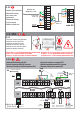
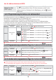
5.5. SCU
5.5.1
Elektrische Verbindungen mit RJ45
Electrical connections with RJ45 connector
Connexions électriques à l'aide du connecteur RJ45
Connessioni elettriche a connettore RJ45
Elektrische aansluitingen met RJ45 connector
Połączenie elektryczne ze złączem RJ45
5.5.2
Zusätzliche Audio Inneneinheiten
Additional audio terminals
Terminale audio adizionale
Extra audio terminals
Dodatkowe terminale audio
5.4.5
21
GNV
JP
Vin
P
GND
CD
+14
GNV
Vout
Uv
GND
CD
+14
+12
GND
CD
Vin
+14
+Uv
LA
LA/C
LC
SWC
N F
2 x
0.75 mm²
AUX1
AUX2
BAT
+
1.6A
Vcam
GND
Vcam
set
Vcam
Vcam
VPA
2 x
0.75 mm²
UTP cat5e (AWG 24)
SC
U
3 x
0
,
7
5 m
m
²
2 x
6
Aa
.c
.
+14V
GNV
Vin
1
2
3
4
BA
TTE
R
Y
1
2V
m
a
x.7
Ah
max. 1Ad.c.
LCK
max. 24Vd.c./a.c.
max. 1A d.c./a.c.
AUX
BAT
-
2 x
0.75 mm²
UTP cat5e
(AWG 24)
BAT
2
3
0 V
a
.c.
5
0
H
z
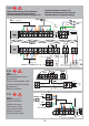
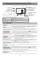
VTA (3.1.1) / VCB
(3.1.2, 3.1.3)
Postes intérieurs audio
supplémentaires
Türklingel
Doorbell
UTP cat5e
(AWG 24)
UTP cat5e
(AWG 24)
V
out
GN
Vo
ut
Vin
G
N
Vi
n
+
U
V
G
ND
C
D
+
14
D
BL
2
D
BL1
VTA 7”
ATA
audio
1
2
3
4
1
2
3
4
SCU (3.1.1) /
VCB(3.1.2, 3.1.3)
GND
C
D
+14
DB
L2
DB
L1
1
1
2
4
3
G
N
D