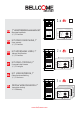
DE 7” VIDEOTÜRSPRECHANLAGEN SET Name 1 Benutzerhandbuch 1, 2, 3 Familien ok EN KIT VIDEO DOOR PHONE, 7” FR KIT INTERPHONE VIDÉO, 7” User manual 1, 2, 3 Families 2x Manuel d'utilisation 1, 2, 3 Familles Name 2 Name 1 IT KIT VIDEO-CITOFONO, 7” Il manuale dell'utente 1, 2, 3 Famiglie ok ok NL PL KIT VIDEOINTERFON, 7” Gebruikershandleiding 1, 2, 3 Gezinnen 3x ZESTAW WIDEODOMOFON 7” Instrukcja obsługi 1-2-3 Rodziny Name 3 Name 2 Name 1 ok ok ok www.bellcome.
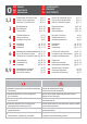
0 1,2 3 4 5 6 7 8,9 IT CONTENUTO NL INHOUD PL SPIS TREŚCI DE INHALT EN CONTENTS FR SOMMAIRE DE EN FR DE EN FR DE EN FR DE EN FR DE EN FR DE EN FR DE EN FR Eigenschaften & Inhalt des sets Features & Kit components Fonctions & Contenu du kit pg. 1...8 pg. 1...8 pg. 1...8 NL pg. 9...10 pg. 9...10 pg. 9...10 NL pg. 11 pg. 12 pg. 13 NL pg. 17...23 pg. 17...23 pg. 17...23 NL Benutzung der videotürsprechanlage pg. 24...29 pg. 32...
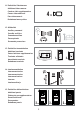
1 DE EIGENSCHAFTEN EN FEATURES FR FONCTIONS IT NL PL 1. Ruf Call Appel Chiamata Oproep Połaczenie 2. Video(7”) + Antwort Video(7”) + Answer Affichage vidéo (7”) + Réponse Video(7'') + Risposta Video (7”) + Antwoorden Wideo (7”) + Odpowiedz 3. Freisprechen Hands-free talk Communication mains-libres Conversazione senza mani Handsfree gesprek Rozmowa hands-free 4. Zugangsgewährung Access granting Contrôle d'accès Concedere accesso Toegang geven Przyznanie dostepu 5.
6. Bilder Speicher Pictures memory Mémoire d'images Memorizzare delle immagini Afbeeldingen opslaan 100 x Zapisywanie obrazów 7. Lautstärke Volume levels Volume réglable Livelli di volume Volume niveaus MUTE 1 7 Poziom głośności 8. Einstellen der Anrufdauer 1 x 5 sec 2 x 5 sec 3 x 5 sec Setting the ringing duration Durée de la sonnerie réglable Sciegliere la durata della chiamata De duur van de beltoon instellen x Ustawianie trwania połączenia 9.
11. Zusätzliche Videokameras Additional video cameras Caméras vidéo supplémentaires Camere video adizionali Extra videocamera's 4 x Dodatkowe kamery wideo 12. Hilfsbefehl Auxiliary command Contrôle auxiliaire Comando aussiliare Extra opdracht Sterowanie pomocnicze 13. Zusätzliche Inneneinheiten Additional terminals Postes intérieurs supplémentaires Terminale adizionale Aanvullende terminals 1 1 ok x video 7” Dodatkowe terminale 3 x video 3.5” x audio 14.
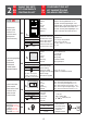
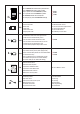
2 DE INHALT DES SETS EN KIT COMPONENTS FR CONTENU DU KIT Außeneinheit Outdoor panel Platine de rue Pannello esterno Buitenpaneel Panel zewnetrzny Name 1 VPA 1x 294 x 144 x 53 mm 1,52 kg - 30oC … + 60oC v Stromversorgungseinheit Central unit Unité centrale SCU Unità centrale Centrale eenheid Jednostka Centralna 12 … 14 Vd.c. 1x 130 x 141 x 73 mm 0,4 kg 0oC … + 45oC v 14 V- GND : 14 Vd.c./2 Ad.c. Uv - GNV : 14 Vd.c./0.5 Ad.c. Vcam - GND : 12 Vd.c./0.4 Ad.c.
2x Außeneinheit Outdoor panel Platine de rue Pannello esterno Buitenpaneel Panel zewnetrzny Name 2 Name 1 VPA 1x 294 x 144 x 53 mm 1,52 kg - 30oC … + 60oC v Stromversorgungseinheit Central unit Unité centrale SCU Unità centrale Centrale eenheid Jednostka Centralna 12 … 14 Vd.c. 1x 130 x 141 x 73 mm 0,4 kg 0oC … + 45oC v 14 V- GND : 14 Vd.c./2 Ad.c. Uv - GNV : 14 Vd.c./0.5 Ad.c. Vcam - GND : 12 Vd.c./0.4 Ad.c.
3x Außeneinheit Outdoor panel Platine de rue Pannello esterno Buitenpaneel Panel zewnetrzny Name 3 Name 2 Name 1 VPA 1x 294 x 144 x 53 mm 1,52 kg - 30oC … + 60oC v 12 … 14 Vd.c. PROG S1 S2 S3 STROMVERSORGUNGSEINHEIT (SCU.VDR02.BLW) Stromversorgungseinheit Central unit Unité centrale SCU Unità centrale Centrale eenheid Jednostka Centralna SCHLOSSÖFFNUNGS- 1 2 3 4 EINGANG: 230V Wechselspannung 50Hz, 0.4A ZEIT 5 AUSGANG 1: 14V, 2A Gleichspannung (S1) (sekunden) 6 AUSGANG 2: 14V, 0.
Zusatzprodukte (seperat zu erwerben) Additional products (separately purchased) Produits supplémentaires (vendus séparément) 1x BAT 1x 12V/7Ah 1x LCK Gleichstrom (DC) oder Wechselstrom (AC) Schloss Direct current (DC) or Alternative current (AC) lock Serrure électrique à courant continu (CC) ou alternatif (CA) 12Vd.c., 1 Ad.c. max. 24Va.c., 1 Aa.c. Serratura per corrente continuo (d.c.) o alternata (a.c.
VPA 3x 1x 4x VSB.4DN02.
3 IT NL PL DE BLOCKDIAGRAMME EN BLOCK DIAGRAMS FR SCHÉMAS-BLOC 3.1.1 DIAGRAMMA BLOCCO BLOKSCHEMA'S SCHEMAT BLOKOWY 230 Va.c., 50 Hz 3 x 0.75 mm2 UTP cat5e Vcam 2 x 6Aa.c. (AWG 24) PVB 12V /7Ah 2 x 0.75 mm UTP cat5e PROG LCK S1 UTP cat5e S3 SCHLOSSÖFFNUNGS- 1 2 3 4 EINGANG: 230V Wechselspannung 50Hz, 0.4A ZEIT 5 AUSGANG 1: 14V, 2A Gleichspannung (S1) (sekunden) 6 AUSGANG 2: 14V, 0.
3.2. Zusätzliche Inneneinheiten Additional terminals Postes intérieurs supplémentaires SCU (3.1.1) / VCB(3.1.2, 3.1.3) UTP cat5e UTP cat5e (AWG 24) (AWG 24) VTA SCU (3.1.1) / VCB(3.1.2, 3.1.3) VTA2 UTP cat5e UTP cat5e (AWG 24) (AWG 24) Terminali adizionali Extra terminals Dodatkowe terminale VTA SCU (3.1.1) / VCB(3.1.2, 3.1.3) VTT2 UTP cat5e UTP cat5e (AWG 24) (AWG 24) ATA2 VTA 3.3. PVB UTP cat5e (AWG 24) PVB Vcam3 VSB.4DN02.
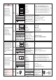
4 SICHERHEITSHINWEISE während der Installation DE 1. ACHTUNG! Die Installation, die Wartung und die Verbindung zum 230V / 50Hz Netz von der Stromversorgungseinheit (SCU) darf nur von autorisiertem Personal durchgeführt werden! 2. ACHTUNG! Es ist ZWINGEND erforderlich, ein 3 x 0,75 mm Kabel und 2 automatische Sicherungen (6A) zur Energieversorgung der Stromversorgungseinheit ("SCU") 230V / 50Hz Netz zu nutzen. 3.
EN 4 SAFETY INSTRUCTIONS during installation 1. ATTENTION! The installation, the maintenance and the connection to the 230V/50Hz network of the central unit (SCU) will be carried out only by authorized personnel! 2. ATTENTION! It is MANDATORY to use a 3 x 0,75 mm2 cable and 2 automatic fuses (6A) for power supplying the central unit (SCU) from the 230V/50Hz network. 3.
4 CONSIGNES DE SÉCURITÉ pendant l'installation FR 1. ATTENTION! L'installation, l'entretien et le branchement de l'unité centrale (SCU) au réseau de 230V/50Hz seront faites uniquement par du personnel autorisé! 2. ATTENTION! Il est obligatoire d'utiliser un câble de 3 x 0,75 mm2 et 2 fusibles automatiques (6A) pour alimenter l'unité centrale (SCU) du réseau de 230 V/50 Hz. 3.
IT 4 ISTRUZIONI DI SICUREZZA durante il montaggio 1. ATTENZIONE! Il montaggio, la manutenzione e la connessione dell'unità centrale (SCU) alla rete di 230V/50 Hz va eseguita soltanto da persone autorizzate! 2. ATTENZIONE! È imperativo l'uso di un cavo di 3 x0.75 e di 2 dispositivi di sicurezza (fusibili) automatici (6A) per l'alimentazione dell'unità centrale (SCU) dalla rete di 230V/50 Hz. 3.
4 VEILIGHEIDSINSTRUCTIES tijdens de installatie NL 1. LET OP! Het installeren, onderhoud en aansluiten van de centrale eenheid (SCU) op het 230V/50Hz netwerk mag alleen worden gedaan door bevoegd personeel! 2. LET OP! Het is verplicht om een kabel van 3 x 0,75 mm en 2 automatische zekeringen (6A) te gebruiken voor de stroomtoevoer van de centrale eenheid (SCU) van het 230V/50Hz netwerk. 3.
PL 4 ZASADY BEZPIECZEŃSTWA podczas instalacji 1. UWAGA! Instalacja, utrzymanie i podłączenie do sieci 230V / 50Hz jednostki centralnej (SCU) będą wykonywane wyłącznie przez autoryzowany personel! 2. UWAGA! Jest to obowiązkowe, aby użyć kabla 3 x 0,75 mm i 2 automatyczne bezpieczniki (6A) do zasilania jednostki centralnej (SCU) z sieci 230V / 50Hz. 3.
5 DE EN FR 5.1. Erforderliches Kabel Required cable Le câble nécessaire Il Cavo necessario Vereiste kabel Wymagany kabel IT NL PL INSTALLATION INSTALLATION INSTALLATION INSTALLAZIONE INSTALLATIE INSTALOWANIE ≤ 100 m ≤ 30 m ≤ 50 m VPA SCU UTP (FTP) cat. 5e AWG24 UTP (FTP) cat. 5e AWG24 SCU VTA UTP (FTP) cat. 5e AWG24 UTP (FTP) cat. 5e AWG24 + 3x0.75 mm2 UTP (FTP) cat. 5e AWG24 + 3x0.75 mm2 UTP (FTP) cat. 5e AWG24 + 3x0.75 mm2 LCK 2 (3) x 0.75 mm2 2 (3) x 0.
5.2.3 Aufputz Version Surface version Version en surface Versione in superficie Oppervlekversie Wersja powierzchniowa 1.5 cm Protezione antifurto. Avitate completamente Torx 2! Diefstalbeveiliging. Torx 2 volledig inschroeven! Ochrona przed kradzieżą. Zakręcić całkowicie Torx 2! Anti Diebstahl Schutz. Schrauben Sie die Torx 2 fest! Antitheft protection. Screw the Torx 2 completely! Protection antivol. Visser complètement Torx 2 ! 5.2.
5.3.2 Connessioni elettriche a connettore RJ45 Elektrische aansluitingen met RJ45 connector Połączenie elektryczne ze złączem RJ45 Elektrische Verbindungen mit RJ45 Electrical connections with RJ45 connector Connexions électriques à l'aide du connecteur RJ45 (FAKULTATIV) VTA 1 VTA 2 +Uv +14 GND UTP cat5e (AWG 24) 2 +Uv UTP cat5e (AWG 24) UTP cat5e (AWG 24) SCU 5.3.
5.4. VTA 5.4.1 Aufputz Surface En surface Su superficie Oppervlak Na powierzchni 170 cm 135 cm Einbau der Video Inneneinheit Installation of the video terminal Installation du poste intérieur vidéo Installazione del Terminale video Installeren van de video terminal Instalacja terminala wideo ≈20 cm UTP cat5e (AWG 24) 5.4.
5.4.5 GNVout Zusätzliche Audio Inneneinheiten Additional audio terminals Postes intérieurs audio supplémentaires +UV CD DBL2 +14 1 DBL2 2 DBL1 UTP cat5e (AWG 24) +14 1 Türklingel Doorbell CD 1 3 4 GND 2 GND 2 Vin 3 GND 3 GNVin 4 UTP cat5e (AWG 24) Terminale audio adizionale Extra audio terminals Dodatkowe terminale audio 4 Vout SCU (3.1.1) / VCB(3.1.2, 3.1.3) 1 audio ATA DBL1 VTA 7” 5.5. SCU 1 A 2 UT HORIZE D 5.5.
5.5.3 Connessioni elettriche a connettori a vite Elektrische aansluitingen met schroef connector Połączenia elektryczne ze złączami śrubowymi Elektrische Verbindungen mit Schraubklemmen Electrical connections with screw connectors Connexions électriques à l'aide des connecteurs à vis Vcam UTP cat5e 230 Va.c. 50Hz 2 x 6Aa.c. (AWG 24) JP set Vcam 3 4 2 3 2 1 1 3 x 0,75 mm² 4 Vin GNV Vin CD +12 GND +14 1.
5.6. Verificate le tensioni di alimentazione (SCU connesso a 230 Va.c.) Überprüfen der Spannung (SCU verbunden mit 230 Va.c.) Controle van toevoerspanningen (SCU aangesloten op 230 V a.c.) Checking the voltages (SCU connected to 230 Va.c.) Vérification des tensions d'alimentation (SCU branchée à 230 V CA) Sprawdzanie napięcia zasilania (SCU podłączony do 230 Va.c.) 3.0 GNV 4.8Vd.c. 2 12V DBL2 +14V CD +UV GND VTA/VCB Vin GNVin 3 Vout 14.3Vd.c. V 3.0 23 4.8Vd.c. 14.3Vd.c.
6 DE BENUTZUNG DER VIDEOTÜRSPRECHANLAGE 6.1. SICHERHEITSHINWEISE während des Gebrauchs è è Schlagen Sie nicht mit harten Gegenständen auf die Produkte. Schützen Sie die Produkte vor Kalk und Staub während der Renovierung. 6.2. Bedeutung der akustischen Signale/Verwendung der Tasten [BEEP] Kurzer Bestätigungston mit einem hohen Ton. 2x[ BEEP [ BEEEEP ] ] Zwei kurze Beep mit einem hohen Ton. Langer Bestätigungston mit einem hohen Ton. [BEEEEP] Langer Störungs Beep mit niedrigem Ton.
Bedeutung der LEDs an der SCU BUTTON PROG LED PROG LED S1 LED S2 LED S3 Das System ist nicht an das 230 Va.c./50 Hz Netz angeschlossen. Langes Drücken ROT GRÜN GRÜN GRÜN GRÜN System Ok, angeschlossen an 230Va.c./50 Hz Netz. Programmiermodus (Das Kit wurde bereits programmiert) Wenn eine Batterie an der SCU angeschlossen ist sind folgende zusätzliche Signale nur für S3 LED: GRÜN GRÜN Das System ist nicht an das 230Va.c./50 Hz Netz angeschlossen. Die Batterie funktioniert.
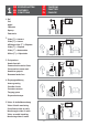
Nur für Außeneinheiten mit RFID ZUGANG mit TAG (RIFD Zugang) Das Symbol zeigt den RFID Tag Lesebereich an. Die Tags sind bereits vorprogrammiert. Wenn Sie diese benutzen, ertönt an der Außeneinheit eine Tonfolge für die Bestätigung, und das Symbol blinkt grün. 6.4.2 Programmierung der Adresse der Außeneinheit Die Außeneinheit ist bereits mit Adresse 1 programmiert, dies ist für die einwandfreie Funktion notwendig.
6.5. Benutzung der Video Inneneinheit (VTA) Antworten + Audio-, Videoüberwachung (Klingeltoneinstellung) Bildergedächtnis Interkommunikation (zwischen 2 x 7” video 1 x 7” video und 1 x 3.5” video 1 x 7” video und bis zu 3 x audio) AUX Befehl (Garagentor, Außenbeleuchtung, etc..
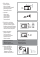
ZUGANG GEWÄHREN Inneneinheit im Stand-by oder während Ruf, Gespräch oder Überwachungsmodus BILDER MACHEN Inneneinheit während Ruf, Gespräch oder Überwachungsmodus FOTOS ANSEHEN FOTOS LÖSCHEN Inneneinheit im Stand-by Im Stand-by Lange drücken von . Während Anruf, Gespräch oder Überwachung Kurze Berührung von zu jeder Zeit. Der Zugang wird auch mit einem speziellen Bestätigungston akustisch signalisiert, und das Gespräch wird um 10 Sek. verlängert.
Gleichzeitiges, langes Drücken von und [BEEEEP]. Die Inneneinheit ist im Einstellungsmodus. Sie haben 2 Min. Schritt 1 um alle 3 Einstellungen zu ändern, die Reihenfolge ist nicht wichtig. Wir empfehlen die folgende Sequenz. Um die KLINGELTON einzustellen, kurze Berührungen von : 1. kurze Berührung von Es wird der erste Klingelton abgespielt. 2. kurze Berührungen von Es wird der zweite Klingelton abgespielt. Es wird der dritte Klingelton abgespielt, Schritt 2 3.
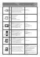
DE No. 1. 2. 7 FEHLERDIAGNOSE Problem Das System funktioniert nicht. Das System ist OK. SCU signalisiert S1 S2 S3 PROG S1 Grün S2 Grün S3 PROG S3 Grün S3 Rot 3. Das System funktioniert ohne Video für begrenzte Zeit. 4. Das System funktioniert nicht. 5. Das System funktioniert, aber die gemessene Spannung der VTA Steckverbindungen ist niedriger als 11 Vd.c. +14 V – GND < 11 V +Uv – GND < 11 V S1 S2 S3 Grün PROG 6. Keine Batterie (max. 7 Ah) mit der Stromversorgungseinheit (SCU) verbunden.
8. Ein störendes Geräusch während des Redens an der Inneneinheit (VTA) ist vorhanden. Die anderen Funktionen sind OK. S1 Grün S2 Grün S3 PROG 9. Das Display der Inneneinheit (VTA) ist schwarz, (off) während dem Ruf und des Gesprächs. S1 Grün S2 Rot S3 PROG 10. Das Display der Inneneinheit (VTA) ist blau während dem Ruf und des Gesprächs. S1 Grün S2 Grün S3 PROG Die Farbe des Bildes der Inneneinheit (VTA) ist 11. immer verschwommen.
6 EN USE OF THE VIDEO DOOR PHONE 6.1. Safety instructions during use è è DO NOT HIT the products with hard objects. PROTECT THE PRODUCTS against lime and dust during renovation. 6.2. Significance of the acoustic signals / use of the keys [BEEP] Short confirmation beep with a high tone. 2x[ BEEP [ BEEEEP ] ] Sequence of 2 short beeps with a high tone for confirmation. Long confirmation beep with a high tone. [BEEEEP] Long error beep with a low tone.
Significance of LEDs signaling on SCU BUTTON PROG LED PROG LED S1 LED S2 LED S3 The system is not connected to the 230 Va.c./ 50 Hz network. Long press RED GREEN GREEN GREEN GREEN The system is OK, connected to the 230 Va.c./ 50 Hz network. Programming mode (The kit is already programmed.) When a battery is connected to SCU, there are the following additional signals only for S3 LED: GREEN GREEN The system is not connected to the 230 Va.c./ 50 Hz network. The battery is functional.
Only for Outdoor panel with RFID ACCESS with TAG (RFID access) The symbol indicates the RFID tag reading area. The tags are already memorized. When used, the locks opens, the panel emits a sequence of beeps for confirmation and the symbol blinks green. 6.4.2 Programming the panel address The panel is already programmed with address 1, which is mandatory for the correct functioning of the system. The programming is necessary only if: -The address 1 is changed by mistake during installation.
6.5. Use of the video terminal (VTA) Call answering + Audio-Video Monitoring (ringtone setting) Taking pictures Intercommunication Between 2x7” video 1x7” video and 1x3.5” video 1x7” video and up to 3 x audio AUX command (auto gate, external lighting etc...
ACCESS GRANTING Terminal in stand-by or during call, talk or monitoring PICTURES TAKING Terminal during call, talk or monitoring VIEW PICTURES / DELETE PICTURES Terminal in stand-by From stand-by Long press of . During call, talk or monitoring Short touch of any time. The access is signaled acoustically also, with a specific confirmation song and the bidirectional audio communication remains opened 10 more sec. Implicitly, for each call from the outdoor panel one picture is taken.
Simultaneous long press of and [BEEEEP]. The terminal goes in setting mode. You have 2 min. to Step 1 set all the 3 features, in whatever order you choose. We suggest the following sequence. For setting the RINGTONE, short touches of : 1st short touch of The terminal plays the 1st ringtone. 2nd short touch of The terminal plays the 2nd ringtone. Step 2 3rd short touch of The terminal plays the 3rd ringtone and so on up to all 5 ringtones available.
EN 7 TROUBLESHOOTING No. Problem 1. The system doesn`t work. 2. The system works OK. SCU signals S1 S2 S3 PROG S1 green S2 green S3 PROG S3 green S3 red S1 S2 S3 green PROG 3. The system works without video, for a limited time. 4. S1 red The system doesn`t work. S2 red or green S3 PROG 5. The system works OK, but the voltages measured to the VTA connectors are lower than 11 Vd.c. +14 V – GND < 11 V +Uv – GND < 11 V S1 green S2 green S3 PROG (ch. 5.5) 6. 7.
8. There is a disturbing noise during talk on the terminal (VTA). The other features are OK. S1 green S2 green S3 PROG 9. The video display of the terminal (VTA) is Black (off) during call and talk. S1 green S2 red S3 PROG 10. The video display of the terminal (VTA) is Blue during call and talk. S1 green S2 green S3 PROG The COLOR video image of the terminal 11. (VTA) is blurred all the time. S1 green S2 green S3 PROG The video image of the 12. terminal (VTA) is BLACK & WHITE.
6 FR UTILISATION DE L'INTERPHONE VIDÉO 6.1. CONSIGNES DE SÉCURITÉ pendant l'utilisation NE PAS FRAPPER le dispositif avec des objets durs. PROTÉGER le dispositif contre la chaux et la poussière pendant les travaux de rénovation. è è 6.2. Signification des signaux acoustiques / utilisation des touches [BEEP] Bip court à haute fréquence pour confirmation. 2x[ BEEP [ BEEEEP ] ] Séquence de 2 bips courts à haute fréquence pour confirmation. Bip long à haute fréquence pour confirmation.
Signification des clignotements des LED de SCU BUTTON PROG LED PROG LED S1 LED S2 LED S3 Le système n'est pas branché au réseau de 230 V / 50 Hz. Appui long ROUGE VERT VERT VERT GREEN Le système est en bon état, branché au réseau de 230 V CC / 50 Hz. Mode de programmation (le kit est déjà programmé). Lorsqu'un accumulateur est connecté à SCU, les clignotements suivants de la LED S3 s'ajoutent : VERT VERT VERT VERT ROUGE Le système n'est pas branché au réseau de 230 V CC / 50 Hz.
Valable uniquement pour la platine de rue à RFID ACCÈS À BADGE (accès RFID) Le symbole indique la zone de lecture du badge RFID. Les badges RFID sont déjà enregistrés. Quand on les utilise, la serrure s'ouvre, la platine de rue émet une séquence de bips de confirmation et le symbole clignote en vert. 6.4.2 Programmation de l'adresse de la platine de rue La platine de rue est déjà programmée avec l'adresse 1, chose obligatoire pour le fonctionnement correcte du système.
6.5. Utilisation du poste intérieur vidéo (VTA) Réponse à un appel + Surveillance audio-vidéo (définir la mélodie d'appel) Prise d'images Intercommunication (entre 2 x 7” vidéo 1 x 7” vidéo et 1 x 3.5” vidéo 1 x 7” vidéo et jusqu'à 3 x audio) Permission d'accès (définir la durée de l'appel) Contrôle AUX (portail, éclairage extérieur etc.
PERMISSION D'ACCÈS Poste intérieur en veille ou au milieu d'un appel, d'une conversation ou de la surveillance PRISE D'IMAGES Poste intérieur au milieu d'un appel, d'une conversation ou de la surveillance VISUALISATION / SUPPRESSION DES IMAGES Poste intérieur en veille En veille Appuis long sur la touche . Pendant un appel, une conversation ou la surveillance Appui court de la touche à tout moment.
Étape 1 Appui long et simultané sur les touches et [BEEEEP]. Le poste intérieur entre dans le mode réglage. Vous avez 2 min. pour régler les 3 paramètres dans l'ordre que vous préférez. Nous recommandons la séquence suivante. Étape 2 Pour régler LA MÉLODIE DE L'APPEL, appuis courts sur la touche : Premier appui court sur la touche La première mélodie joue. Deuxième appui court sur la touche La deuxième mélodie joue. Troisième appui court sur la touche La troisième mélodie joue.
FR No. 1. 2. 7 DÉPANNAGE Signalisations SCU S1 Le système ne fonctionne S2 S3 pas. PROG S1 Vert S2 Vert S3 PROG Le système fonctionne correctement. S3 Vert Problème S3 Rouge 3. 4. 5. Le système fonctionne sans image vidéo, pour un temps limité. S1 S2 S3 Vert PROG S1 Rouge Le système ne fonctionne S2 Rouge or Vert S3 pas. PROG Le système fonctionne correctement, mais les tensions mesurées aux bornes du poste intérieur S1 Vert (VTA) sont au-dessous S2 Vert S3 de 11 V CC.
8. La conversation est accompagnée par un bruit fort dans le poste intérieur (VTA). Le reste des fonctions sont en bon état. S1 Vert S2 Vert S3 PROG 9. L'affichage du poste intérieur (VTA) est noir (éteint) pendant l'appel et la conversation. S1 Vert S2 Rouge S3 PROG 10. L'affichage du poste intérieur (VTA) est bleu pendant l'appel et la conversation. S1 Vert S2 Vert S3 PROG L'image COULEUR sur l'affichage du poste 11. intérieur (VTA) est toujours floue.
6 IT L'UTILIZZO DEL VIDEOCITOFONO 6.1. Istruzioni di sicurezza durante l'uso è è Non colpite i prodotti con oggetti duri. Proteggere i prodotti da calce e polvere durante la ristrutturazione. 6.2. Significato dei segnali acustici/utilizzo dei tasti [BEEP] Breve squillo di alta frequenza per la conferma. 2x[ BEEP [ BEEEEP ] ] Sequenza tipo 2 squilli brevi di alta frequenza per la conferma. . Squillo lungo di alta frequenza per la conferma. [BEEEEP] Squillo lungo di bassa frequenza per errore.
Significato della segnalazione dei LED a SCU BUTTON PROG LED PROG LED S1 LED S2 LED S3 L'installazione non è connessa alla rete di 230Vc.a./50Hz. Spingere a lungo ROSSO VERDE VERDE VERDE VERDE L'installazione in regola, connessa alla rete di 230Vc.a./50Hz Modo programmazione (il kit è già programmato) Quando è connessa una batteria a SCU, si aggiunge la seguente segnaletica dei LED S3: VERDE VERDE L'installazione non è connessa alla rete di 230Vc.a./50Hz. La batteria ricaricabile funziona.
Solo per pannello esterno con RFID ACCESSO CON TAG (accesso RFID) Il simbolo indica la zona di lettura della tag RFID. Le TAG sono già memorizzate. Quando sono utilizzate, la serratura si apre, il pannello emette una sequenza di squilli di conferma ed il simbolo lampeggia in verde. 6.4.2 Programmazione dell'indirizzo del pannello Il pannello è già programmato con l'indirizzo 1, d'obbligo per il corRetto funzionamento dell'installazione.
6.5. L'uso del terminale video (VTA) Risposta chiamata + Monitoraggio audio- video (scegliere la suoneria per la chiamata) Concedere l'accesso (scegliere durata chiamata) Il fotografare Intercomunicazione tra 2 x 7” video 1 x 7” video e 1 x 3.5” video 1 x 7” video e fino a 3 x audio Comando AUX (cancello auto, illuminazione esterna, ecc.
CONCESSIONE ACCESSO Terminale in attesa oppure durante la chiamata, la conversazione o il monitoraggio IL FOTOGRAFARE Terminale durante la chiamata, la conversazione o il monitoraggio VIZUALIZZARE/ CANCELLARE LE FOTO Terminale in attesa Dall'attesa Pressione lunga del tasto . Durante la chiamata, la conversazione o il monitoraggio Breve contatto del tasto in qualsiasi momento.
Lungo e simultaneo pressione dei tasti e [BEEEEP]. Il terminale entra nel modo impostazioni. Avete a disposizione Passo 1 2 minuto per impostare tutti i 3 parametri nell'ordine desiderata. Raccomando la seguente sequenza. IMPOSTAZIONI PER CHIAMATA: Per impostare SUONERIA CHIAMATA, brevi contatti del tasto : In primo breve contatto del tasto Si sente la prima suoneria. Al secondo breve contatto del tasto Si sente la seconda suoneria. Passo 2 Al terzo breve contatto del tasto Si sente la terza suoneria.
IT Nr. 7 RIPARAZIONE Problema 1. L'installazione non funziona. 2. L'installazione funziona in regola. 3. L'installazione funziona, senza immagine video, a tempo limitato. 4. L'installazione non funziona. 5. L'installazione in ottimo stato di funzione, ma le tensioni misurate agli connettori del terminale (VTA) sono inferiori a 11 Vc.c. +14 V – GND < 11 V +Uv – GND < 11 V (Cap. 5.6.
8. La conversazione produce grosso rumore nel terminale (VTA). Il resto delle funzioni in regola. S1 Verde S2 Verde S3 PROG 9. Il display del terminale (VTA) è nero (spento) durante la chiamata e la conversazione. S1 Verde S2 Rosso S3 PROG 10. Il display del terminale (VTA) è color blu durante la chiamata e la conversazione. S1 Verde S2 Verde S3 PROG Le connessioni nei morsetti GND non sono fatte regolarmente(strette). Verificate le connessioni GND a VPA, SCU, (VCB) e VTA.
6 NL HET GEBRUIK VAN VIDEO-INTERCOM 6.1. VEILIGHEIDSINSTRUCTIES tijdens gebruik è è SLA NIET met harde voorwerpen op de producten. BESCHERM DE PRODUKTEN tegen kalk en stof tijdens kluswerkzaamheden. 6.2. De betekenis van de akoestische signalen/gebruik van toetsen [BEEP] Korte pieptoon met hoge frequentie ter bevestiging. 2x[ BEEP [ BEEEEP ] ] Opeenvolging van 2 korte tonen met hoge frequentie ter bevestiging.
Betekenis LED signaleringen op SCU BUTTON PROG LED PROG LED S1 LED S2 LED S3 De installatie is niet aangesloten op de 230VAC /50Hz installatie. Lang indrukken ROOD GROEN GROEN GROEN GROEN Het systeem werkt goed, verbonden met het 230 Va.c./ 50 Hz netwerk. Programmeermodus (de kit is al voorgeprogrammeerd) Indien een batterij verbonden is met de SCU, zijn de volgende extra signalen alleen voor de S3 LED: GROEN GROEN Het systeem is niet verbonden met het 230 Va.c./ 50 Hz netwerk.
Alleen voor buitenpaneel met RFID TOEGANG met TAG (RFID toegang) Het symbool geeft het RFID tag leesgebied aan. De tags zijn reeds in het geheugen opgeslagen. Indien gebruikt, opent zich het slot, het paneel geeft een reeks pieptonen ter bevestiging en het symbool knippert groen. 6.4.2 Programmeren van het adres in het paneel Het panel is reeds geprogrammeerd met adres 1, wat noodzakelijk is voor het goed functioneren van het systeem.
6.5. Gebruik van de video terminal (VTA) Oproep beantwoorden + Audio-Video Bewaking (beltoon instelling) Opnames maken Onderlinge communicatie (tussen 2 x 7” video 1 x 7” video en 1 x 3.5” video 1 x 7” video en tot 3 x audio) AUX opdracht (automatisch hek, externe verlichting etc.
TOEGANG VERLENEN Terminal in stand-by of gedurende oproep, gesprek of bewaking BEELDEN OPNEMEN Terminal gedurende oproep, gesprek of bewaking BEELDEN BEKIJKEN / BEELDEN VERWIJDEREN Terminal in stand-by Vanuit stand-by Lange druk op . Gedurende oproep, gesprek of bewaking Korte druk op op ieder moment. De toegang wordt ook akoestisch aangegeven met een specifieke bevestigingsmelodie en de bidirectionele audio communicatie blijft 10 sec. langer geopend.
Stap 1 Gelijktijdig lang indrukken van en [BEEEEP]. De terminal gaat in de instellingsmodus. U heeft 2 min. om alle 3 de parameters in te stellen, ongeacht de volgorde die u kiest. We raden de volgende volgorde aan. Om de BELTOON in te stellen, kort drukken op : 1e korte druk op De terminal speelt de 1e beltoon. 2e korte druk op De terminal spelt de 2e beltoon. Stap 2 3e korte druk op De terminal spelt de 3e beltoon enzovoorts tot alle 5 beschikbare beltonen .
NL Nr. 1. 2. 7 PROBLEMEN VERHELPEN Probleem Het systeem werkt niet Het systeem werkt goed. SCU signalen S1 S2 S3 PROG S1 Groen S2 Groen S3 PROG S3 Groen S3 Rood 3. Het systeem functioneert zonder video, voor een beperkte tijd. 4. Het systeem werkt niet. 5. Het system functioneert goed, maar de gemeten spanningen op de VTA connectoren zijn lager dan 11 Vd.c. +14 V – GND < 11 V +Uv – GND < 11 V (Hfdst. 5.6.) 6. 7. De oproep van het buitenpaneel (VPA) werkt niet. UCD = 0V of 5V (Hfdst. 5.6.
8. Er is een storende ruis tijdens gesprek op de terminal (VTA). De andere functies zijn OK. S1 Groen S2 Groen S3 PROG 9. Het video display van de terminal (VTA) blijft zwart (uit) tijdens oproep en gesprek. S1 Groen S2 Rood S3 PROG 10. Het video display van de terminal (VTA) is blauw tijdens oproep en gesprek. S1 Groen S2 Groen S3 PROG Controleer de GND verbindingen van VPA, SCU, (VCB) en VTA. Bevestig de draden stevig in de connector.
6 PL UŻYWANIE WIDEODOMOFONU 6.1. ZASADY BEZPIECZEŃSTWA podczas użytkowania è è NIE UDZERZAJ w produkty twardymi przedmiotami. CHRONIĆ PRODUKTY przed wapnem i pyłem podczas remontu. 6.2. Znaczenie sygnałów akustycznych / użycie klawiszy [BEEP] Krótki sygnał wysokiej częstotliwości, dla potwierdzenia. 2x[ BEEP [ BEEEEP ] ] Sekwencja 2 krótkie dźwięki o wysokiej częstotliwości dla potwierdzenia Długi dźwięk o wysokiej częstotliwości, dla potwierdzenia.
Znaczenie LED sygnalizujące SCU BUTTON PROG LED PROG LED S1 LED S2 LED S3 Roślina ta jest połączona z 230Vc.a. / 50Hz. Długie naciśnięcie CZERWONY ZIELONY ZIELONY Instalacja jest OK, podłączona do sieci 230Va.c./50Hz. ZIELONY ZIELONY Tryb programowania (zestaw jest już zaprogramowany.) Kiedy bateria jest podłączona do SCU dodaje LED sygnalizacji S3: ZIELONY ZIELONY Roślina ta jest połączona z 230Vc.a. / 50Hz. Bateria jest funkcjonalny.
Tylko dla panelu zewnętrznego z RFID DOSTĘP Z TAG (dostęp RFID) Symbol oznacza obszar czytania znaczników RFID tag. Znaczniki są już zapisane. Gdy są używane, zamek się otwiera, panel emituje sekwencję dźwięków dla potwierdzenia i symbol miga zielony. 6.4.2 Programowanie adresu panelu Panel jest zaprogramowany z adresem 1, jest to obowiązek dla prawidłowego funkcjonowania instalacji. Programowanie jest konieczne tylko, jeżeli: - Adres 1 jest zmieniony przez pomyłkę podczas instalacji.
6.5. Używanie terminalu wideo (VTA) Odebranie połączenie + Monitoring audio-video (ustawienie dzwięku) Robienie zdjęć Komunikacji wewnętrznej (pomiędzy 2 x 7” wideo 1 x 7” wideo i 1 x 3.
UDZIELENIE DOSTĘPU Terminal w trybie stand-by lub w trakcie połączenia, rozmowy monitoringu ROBIENIE ZDJĘĆ Terminal w trakcie połączenia, rozmowy lub monitoroingu WIZUALIZACJA / USUNIĘCIE ZDJĘĆ Terminal w trybie stand-by Z tryby stand-by Długie naciśnięcie przycisku . Podczas połączenia, rozmowy lub monitoringu Krótki dotyk przycisku w każdej chwili. Dostęp jest sygnalizowane dźwiękiem potwierdzającym, zaś dwustronna komunikacji audio, pozostają otwarta przez kolejne 10 sek.
Krok 1 USTAWIENIA DLA POŁĄCZEŃ: Dla ustawienia DZWONKA POŁĄCZENIA, należy nacisnąć krótko przycisk : Pierwszy dotyk przycisku włancza się pierwszy dzwonek Krok 2 Drugi dotyk przycisku włancza się drugi dzwonek Trzeci dotyk przycisku włancza się trzeci dzwonek i tak dalej aż do wszystkich pięciu dzwonków dostępnych. Ten ostatni wysłuchany dzwonek pozostaje ustawiony po 3 sek. po ostatnim naciśnięciu klawisza .
PL 7 ROZWIĄZYWANIE PROBLEMÓW Nr. Problem 1. Instalacja nie działa. 2. Instalacja działa OK. Sygnały SCU S1 S2 S3 PROG S1 zielony S2 zielony S3 PROG S3 zielony S3 red 3. 4. 5. Instalacja funkcjonuje, bez obrazu wideo, w ograniczonym czasie. Instalacja nie działa. Instalația funkcjonujeOK, zaś mierzone napięcie w złaczach zaciskowych terminalu (VTA) są poniżej 11 Vc.c.
8. Rozmowie towarzyszy duży S1 zielony S2 zielony hałas w terminalu (VTA). S3 Pozostałe funkcje są OK. PROG 9. Ekran terminalu (VTA) jest czarny (wyłączony) w trakcie rozmowy i połączenia. S1 zielony S2 czerwony S3 PROG Wyświetlacz terminalu (VTA) jest niebieski podczas połączenia i rozmowy. S1 zielony S2 zielony S3 PROG Obraz COLOR na ekranie 11. terminalu (VTA) jest zamazany przez cały czas. S1 zielony S2 zielony S3 PROG Obraz na ekranie 12. terminalu (VTA) jest biało –czarny.
DE BELLCOME ist eine Marke von ELECTRA. EN BELLCOME is a trademark of ELECTRA. FR BELLCOME est une marque d`ELECTRA. IT BELLCOME è un marchio di fabbrica di ELECTRA. NL BELLCOME is een handelsmerk van ELECTRA. PL BELLCOME jest znakiem towarowym firmy ELECTRA. Designed and Manufactured by ELECTRA Made in EU 06.2016 USM.KA7.123.