
User manual

The installation was made with a
different cable from the one
recommended, with a higher
resistance - >8W /100m.
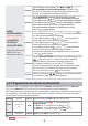
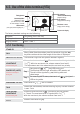
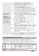
5.
The system works OK,
but the voltages measured
to the VTA connectors are
lower than 11 Vd.c.
+14 V – GND < 11 V
+Uv – GND < 11 V
(ch. 5.5)
S1 green
S2 green
S3
PROG
Only 1 wire connected on +14V
and GND terminals, instead of 2
wires, as shown in the connection
diagram.
The cable length in the system
is higher than 150 m.
We recommend the installation of
a video amplifier (DVA) before or
after SCU. An additional cable of
2
3 x 0,75 mm is required.
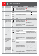
6.
The call from the
outdoor panel (VPA)
doesn`t function.
U = 0V or 5V
CD
(ch. 5.5)
The CD connection could be:
- incorrectly connected or in short
circuit with +14V, +Uv, GND or GNV
- interrupted or not connected to
VPA, (VCB), SCU or VTA.
Check CD everywhere in the
system and correct any errors.
The 2nd wire must be connected
to +14V or GND, as shown in
the connection diagram.
S1 green
S2 green
S3
PROG blinking
red
VPA is not programmed with
address 1.
Program VPA with address 1, see the
procedure (ch. 6.4.2.). If additional panels
are installed, they must be programmed
with different address – 2, 3 or 4.
S3 red
The battery is during charging
or defect.
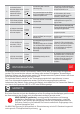
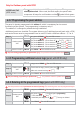
2.
The system works OK.
S1 green
S2 green
S3
PROG
System OK.
S3 green
With battery (max. 7 Ah) connected to
the central unit (SCU).
The battery must be replaced if the S3
LED doesn`t turn green after 5 hours.
3.
The system works without
video, for a limited time.
The system has no power supply from
the 230 Va.c./ 50 Hz network or the
fuses are burned (the systems works
only on battery, with the basic features:
door opening and talk).
Check the power supply of SCU from
the 230 Va.c./ 50 Hz network or the
fuses status.
Check FUSE on the entry in SCU.
S1
S2
S3 green
PROG
No battery (max. 7 Ah) connected
to the central unit (SCU).
4.
The system doesn`t work.
S1 red
S2 red or green
S3
PROG
Short circuit between +14V and
GND and/or GNV and +Uv.
Check the connections between +14V
and GND and/or GNV and +Uv.
Correct any errors.
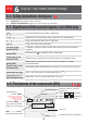
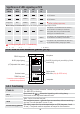
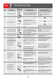
7
No.
Problem
SCU signals
Possible causes Potential solutions
1.
The system doesn`t work.
S1
S2
S3
PROG
The system has NO power supply from
the 230 Va.c./ 50 Hz network and there
is no battery connected to the SCU.
Check the power supply of SCU from
the 230 Va.c./ 50 Hz network or the
fuses status. Check FUSE on the
entry in SCU.
TROUBLESHOOTING
EN
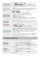
7.
The terminal (VTA)
doesn`t ring when
called from the
outdoor panel (VPA).
S1 green
S2 green
S3
PROG
The CD connection may be interrupted
between SCU, (VCB) and VTA.
The terminal (VTA) doesn`t
BEEP
signal with [ ] when the keyboard is
touched.
Program VTA with the correct address,
see the procedure (ch. 6.5.3.).
Check CD connection of SCU, (VCB) and
VTA and the continuity of the wire.
Correct any errors.
VTA is not programmed with the correct
address.
Check +14, GND connections of SCU,
(VCB) and VTA and the continuity of
the wire. Correct any errors.
38