
Technical data


INSTALLATION - 90CM
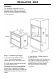
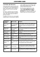
Dimensions
Theapplianceisdesignedtotintoa
standard 600mm wide housing unit, with
minimum internal dimensions as shown.
Note:Allsizesarenominal,somevariation
is to be expected.
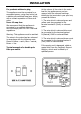
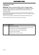
Step 2 : Connect to gas supply
1. The inlet to the appliance is ISO 7
- Rp ½” internal thread situated
towards the top right hand rear corner.
2. Fit the bayonet connection to the wall
in shaded area as shown.
The shaded area shown is applicable to
installations in minimum depth cabinets.
If more room is available, the bayonet
xingareacanbeextended,providedthat
theexibletubedoesnotobscurethefan
intake.
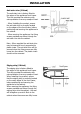
3. Use a 900mm - 1125mm length of
exibleconnector.
Theexibleconnectorshallbettedsuch
that it cannot come into contact with a
moveable part of the housing unit (eg;
drawer)anddoesnotpassthrough
any space susceptible of becoming
congested.