ST72104Gx, ST72215Gx, ST72216Gx, ST72254Gx 8-BIT MCU WITH SINGLE VOLTAGE FLASH MEMORY, ADC, 16-BIT TIMERS, SPI, I2C INTERFACES ■ ■ ■ ■ ■ ■ ■ Memories – 4K or 8K bytes Program memory (ROM and single voltage FLASH) with read-out protection and in-situ programming (remote ISP) – 256 bytes RAM Clock, Reset and Supply Management – Enhanced reset system – Enhanced low voltage supply supervisor with 3 programmable levels – Clock sources: crystal/ceramic resonator oscillators or RC oscillators, external cloc
Table of Contents 1 INTRODUCTION . . . . . . . . . . . . . . . . . . . . . . . . . . . . . . . . . . . . . . . . . . . . . . . . . . . . . . . . . . . . . . 6 2 PIN DESCRIPTION . . . . . . . . . . . . . . . . . . . . . . . . . . . . . . . . . . . . . . . . . . . . . . . . . . . . . . . . . . . . 7 3 REGISTER & MEMORY MAP . . . . . . . . . . . . . . . . . . . . . . . . . . . . . . . . . . . . . . . . . . . . . . . . . . . 10 4 FLASH PROGRAM MEMORY . . . . . . . . . . . . . . . . . . . . . . . . . . . . . . .
Table of Contents 9.4 LOW POWER MODES . . . . . . . . . . . . . . . . . . . . . . . . . . . . . . . . . . . . . . . . . . . . . . . . . . 34 9.5 INTERRUPTS . . . . . . . . . . . . . . . . . . . . . . . . . . . . . . . . . . . . . . . . . . . . . . . . . . . . . . . . . 34 9.6 REGISTER DESCRIPTION . . . . . . . . . . . . . . . . . . . . . . . . . . . . . . . . . . . . . . . . . . . . . . . 34 10 MISCELLANEOUS REGISTERS . . . . . . . . . . . . . . . . . . . . . . . . . . . . . . . . . . . . . . . . . .
Table of Contents 12 INSTRUCTION SET . . . . . . . . . . . . . . . . . . . . . . . . . . . . . . . . . . . . . . . . . . . . . . . . . . . . . . . . . 90 12.1 ST7 ADDRESSING MODES . . . . . . . . . . . . . . . . . . . . . . . . . . . . . . . . . . . . . . . . . . . . . . 90 12.1.1 Inherent . . . . . . . . . . . . . . . . . . . . . . . . . . . . . . . . . . . . . . . . . . . . . . . . . . . . . . . . . 12.1.2 Immediate . . . . . . . . . . . . . . . . . . . . . . . . . . . . . . . . . . . . . . . . . . . . .
Table of Contents 13.9.1 Asynchronous RESET Pin . . . . . . . . . . . . . . . . . . . . . . . . . . . . . . . . . . . . . . . . . 121 13.9.2 ISPSEL Pin . . . . . . . . . . . . . . . . . . . . . . . . . . . . . . . . . . . . . . . . . . . . . . . . . . . . . 123 13.10 TIMER PERIPHERAL CHARACTERISTICS . . . . . . . . . . . . . . . . . . . . . . . . . . . . . . . . . 124 13.10.1 Watchdog Timer . . . . . . . . . . . . . . . . . . . . . . . . . . . . . . . . . . . . . . . . . . . . . . . . 124 13.10.
ST72104Gx, ST72215Gx, ST72216Gx, ST72254Gx 1 INTRODUCTION The ST72104G, ST72215G, ST72216G and ST72254G devices are members of the ST7 microcontroller family. They can be grouped as follows: – ST72254G devices are designed for mid-range applications with ADC and I²C interface capabilities. – ST72215/6G devices target the same range of applications but without I²C interface. – ST72104G devices are for applications that do not need ADC and I²C peripherals.
ST72104Gx, ST72215Gx, ST72216Gx, ST72254Gx 2 PIN DESCRIPTION Figure 2.
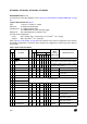
ST72104Gx, ST72215Gx, ST72216Gx, ST72254Gx PIN DESCRIPTION (Cont’d) For external pin connection guidelines, refer to Section 13 "ELECTRICAL CHARACTERISTICS" on page 96. Legend / Abbreviations for Table 1: Type: I = input, O = output, S = supply Input level: A = Dedicated analog input In/Output level: C = CMOS 0.3VDD/0.7VDD, CT= CMOS 0.3VDD/0.
ST72104Gx, ST72215Gx, ST72216Gx, ST72254Gx Port / Control 18 16 PC1/OCMP1_B/AIN1 I/O CT X ei0/ei1 X X X Port C1 19 17 PC0/ICAP1_B/AIN0 I/O CT X ei0/ei1 X X X Port C0 20 18 PA7 I/O CT HS X X X Port A7 21 19 PA6 /SDAI I/O CT HS X 22 20 PA5 I/O CT HS X 23 21 PA4 /SCLI I/O CT HS X 24 NC 25 NC int PP Main Function (after reset) OD Output ana wpu Input float Output Input Pin Name Type Level SO28 SDIP32 Pin n° ei0 ei0 ei0 ei0 T X Port A6 X T Alternate Function
ST72104Gx, ST72215Gx, ST72216Gx, ST72254Gx 3 REGISTER & MEMORY MAP As shown in the Figure 4, the MCU is capable of addressing 64K bytes of memories and I/O registers. The available memory locations consist of 128 bytes of register location, 256 bytes of RAM and up to 8Kbytes of user program memory. The RAM space includes up to 128 bytes for the stack from 0100h to 017Fh. The highest address bytes contain the user reset and interrupt vectors.
ST72104Gx, ST72215Gx, ST72216Gx, ST72254Gx Table 2. Hardware Register Map Address 0000h 0001h 0002h Block Port C Register Label PCDR PCDDR PCOR 0003h 0004h 0005h 0006h Port B PBDR PBDDR PBOR Port A 00h 1) 00h 00h R/W 2) R/W 2) R/W 2) 00h 1) 00h 00h R/W R/W R/W.
ST72104Gx, ST72215Gx, ST72216Gx, ST72254Gx Address 0031h 0032h 0033h 0034h 0035h 0036h 0037h 0038h 0039h 003Ah 003Bh 003Ch 003Dh 003Eh 003Fh Block Register Label Register Name Reset Status Remarks TACR2 TACR1 TASR TAIC1HR TAIC1LR TAOC1HR TAOC1LR TACHR TACLR TAACHR TAACLR TAIC2HR TAIC2LR TAOC2HR TAOC2LR Timer A Control Register 2 Timer A Control Register 1 Timer A Status Register Timer A Input Capture 1 High Register Timer A Input Capture 1 Low Register Timer A Output Compare 1 High Register Timer A
ST72104Gx, ST72215Gx, ST72216Gx, ST72254Gx 4 FLASH PROGRAM MEMORY ■ ■ ■ ■ Remote In-Situ Programming (ISP) mode Up to 16 bytes programmed in the same cycle MTP memory (Multiple Time Programmable) Read-out memory protection against piracy 4.3 STRUCTURAL ORGANISATION The FLASH program memory is organised in a single 8-bit wide memory block which can be used for storing both code and data constants.
ST72104Gx, ST72215Gx, ST72216Gx, ST72254Gx 5 CENTRAL PROCESSING UNIT 5.1 INTRODUCTION This CPU has a full 8-bit architecture and contains six internal registers allowing efficient 8-bit data manipulation. 5.2 MAIN FEATURES ■ ■ ■ ■ ■ ■ ■ ■ 63 basic instructions Fast 8-bit by 8-bit multiply 17 main addressing modes Two 8-bit index registers 16-bit stack pointer Low power modes Maskable hardware interrupts Non-maskable software interrupt 5.
ST72104Gx, ST72215Gx, ST72216Gx, ST72254Gx CPU REGISTERS (cont’d) CONDITION CODE REGISTER (CC) Read/Write Reset Value: 111x1xxx 7 1 0 1 1 H I N Z because the I bit is set by hardware at the start of the routine and reset by the IRET instruction at the end of the routine. If the I bit is cleared by software in the interrupt routine, pending interrupts are serviced regardless of the priority level of the current interrupt routine.
ST72104Gx, ST72215Gx, ST72216Gx, ST72254Gx CENTRAL PROCESSING UNIT (Cont’d) Stack Pointer (SP) Read/Write Reset Value: 01 7Fh 15 0 8 0 0 0 0 0 0 7 0 1 0 SP6 SP5 SP4 SP3 SP2 SP1 SP0 The Stack Pointer is a 16-bit register which is always pointing to the next free location in the stack. It is then decremented after data has been pushed onto the stack and incremented before data is popped from the stack (see Figure 7).
ST72104Gx, ST72215Gx, ST72216Gx, ST72254Gx 6 SUPPLY, RESET AND CLOCK MANAGEMENT The ST72104G, ST72215G, ST72216G and ST72254G microcontrollers include a range of utility features for securing the application in critical situations (for example in case of a power brownout), and reducing the number of external components. An overview is shown in Figure 8. See Section 13 "ELECTRICAL CHARACTERISTICS" on page 96 for more details.
ST72104Gx, ST72215Gx, ST72216Gx, ST72254Gx 6.1 LOW VOLTAGE DETECTOR (LVD) To allow the integration of power management features in the application, the Low Voltage Detector function (LVD) generates a static reset when the VDD supply voltage is below a VIT- reference value. This means that it secures the power-up as well as the power-down keeping the ST7 in reset.
ST72104Gx, ST72215Gx, ST72216Gx, ST72254Gx 6.2 RESET SEQUENCE MANAGER (RSM) 6.2.1 Introduction The reset sequence manager includes three RESET sources as shown in Figure 11: ■ External RESET source pulse ■ Internal LVD RESET (Low Voltage Detection) ■ Internal WATCHDOG RESET These sources act on the RESET pin and it is always kept low during the delay phase. The RESET service routine vector is fixed at addresses FFFEh-FFFFh in the ST7 memory map.
ST72104Gx, ST72215Gx, ST72216Gx, ST72254Gx RESET SEQUENCE MANAGER (Cont’d) 6.2.2 Asynchronous External RESET pin The RESET pin is both an input and an open-drain output with integrated RON weak pull-up resistor. This pull-up has no fixed value but varies in accordance with the input voltage. It can be pulled low by external circuitry to reset the device. See electrical characteristics section for more details.
ST72104Gx, ST72215Gx, ST72216Gx, ST72254Gx 6.3 MULTI-OSCILLATOR (MO) External RC Oscillator This oscillator allows a low cost solution for the main clock of the ST7 using only an external resistor and an external capacitor. The frequency of the external RC oscillator (in the range of some MHz.) is fixed by the resistor and the capacitor values. Consequently in this MO mode, the accuracy of the clock is dependent on VDD, TA, process variations and the accuracy of the discrete components used.
ST72104Gx, ST72215Gx, ST72216Gx, ST72254Gx 6.4 CLOCK SECURITY SYSTEM (CSS) The Clock Security System (CSS) protects the ST7 against main clock problems. To allow the integration of the security features in the applications, it is based on a clock filter control and an Internal safe oscillator. The CSS can be enabled or disabled by option byte. 6.4.1 Clock Filter Control The clock filter is based on a clock frequency limitation function.
ST72104Gx, ST72215Gx, ST72216Gx, ST72254Gx 6.5 CLOCK RESET AND SUPPLY REGISTER DESCRIPTION (CRSR) Read / Write Reset Value: 000x 000x (XXh) 7 0 0 0 0 LVD RF CSS IE 0 CSS WDG D RF Bit 7:5 = Reserved, always read as 0. Bit 4 = LVDRF LVD reset flag This bit indicates that the last RESET was generated by the LVD block. It is set by hardware (LVD reset) and cleared by software (writing zero). See WDGRF flag description for more details.
ST72104Gx, ST72215Gx, ST72216Gx, ST72254Gx 6.6 MAIN CLOCK CONTROLLER (MCC) The Main Clock Controller (MCC) supplies the clock for the ST7 CPU and its internal peripherals. It allows SLOW power saving mode to be managed by the application. All functions are managed by the Miscellaneous register 1 (MISCR1).
ST72104Gx, ST72215Gx, ST72216Gx, ST72254Gx 7 INTERRUPTS The ST7 core may be interrupted by one of two different methods: maskable hardware interrupts as listed in the Interrupt Mapping Table and a nonmaskable software interrupt (TRAP). The Interrupt processing flowchart is shown in Figure 1. The maskable interrupts must be enabled by clearing the I bit in order to be serviced. However, disabled interrupts may be latched and processed when they are enabled (see external interrupts subsection).
ST72104Gx, ST72215Gx, ST72216Gx, ST72254Gx INTERRUPTS (Cont’d) Figure 15. Interrupt Processing Flowchart FROM RESET I BIT SET? N N Y Y FETCH NEXT INSTRUCTION N IRET? INTERRUPT PENDING? STACK PC, X, A, CC SET I BIT LOAD PC FROM INTERRUPT VECTOR Y EXECUTE INSTRUCTION RESTORE PC, X, A, CC FROM STACK THIS CLEARS I BIT BY DEFAULT Table 5. Interrupt Mapping N° Source Block RESET TRAP Description Register Label Reset Software Interrupt Highest Priority N/A 0 ei0 External Interrupt Port A7..
ST72104Gx, ST72215Gx, ST72216Gx, ST72254Gx 8 POWER SAVING MODES 8.1 INTRODUCTION 8.2 SLOW MODE To give a large measure of flexibility to the application in terms of power consumption, three main power saving modes are implemented in the ST7 (see Figure 16). After a RESET the normal operating mode is selected by default (RUN mode). This mode drives the device (CPU and embedded peripherals) by means of a master clock which is based on the main oscillator frequency divided by 2 (fCPU).
ST72104Gx, ST72215Gx, ST72216Gx, ST72254Gx POWER SAVING MODES (Cont’d) 8.3 WAIT MODE WAIT mode places the MCU in a low power consumption mode by stopping the CPU. This power saving mode is selected by calling the “WFI” ST7 software instruction. All peripherals remain active. During WAIT mode, the I bit of the CC register is forced to 0, to enable all interrupts. All other registers and memory remain unchanged.
ST72104Gx, ST72215Gx, ST72216Gx, ST72254Gx POWER SAVING MODES (Cont’d) 8.4 HALT MODE Figure 20. HALT Mode Flow-chart The HALT mode is the lowest power consumption mode of the MCU. It is entered by executing the ST7 HALT instruction (see Figure 20). The MCU can exit HALT mode on reception of either a specific interrupt (see Table 5, “Interrupt Mapping,” on page 26) or a RESET.
ST72104Gx, ST72215Gx, ST72216Gx, ST72254Gx 9 I/O PORTS 9.1 INTRODUCTION The I/O ports offer different functional modes: – transfer of data through digital inputs and outputs and for specific pins: – external interrupt generation – alternate signal input/output for the on-chip peripherals. An I/O port contains up to 8 pins. Each pin can be programmed independently as digital input (with or without interrupt generation) or digital output. 9.
ST72104Gx, ST72215Gx, ST72216Gx, ST72254Gx I/O PORTS (Cont’d) Figure 21. I/O Port General Block Diagram ALTERNATE OUTPUT REGISTER ACCESS 1 VDD 0 P-BUFFER (see table below) ALTERNATE ENABLE PULL-UP (see table below) DR VDD DDR PULL-UP CONFIGURATION DATA BUS OR PAD If implemented OR SEL N-BUFFER DIODES (see table below) DDR SEL DR SEL ANALOG INPUT CMOS SCHMITT TRIGGER 1 0 EXTERNAL INTERRUPT SOURCE (eix) POLARITY SELECTION ALTERNATE INPUT FROM OTHER BITS Table 6.
ST72104Gx, ST72215Gx, ST72216Gx, ST72254Gx I/O PORTS (Cont’d) Table 7.
ST72104Gx, ST72215Gx, ST72216Gx, ST72254Gx I/O PORTS (Cont’d) CAUTION: The alternate function must not be activated as long as the pin is configured as input with interrupt, in order to avoid generating spurious interrupts. Analog alternate function When the pin is used as an ADC input, the I/O must be configured as floating input. The analog multiplexer (controlled by the ADC registers) switches the analog voltage present on the selected pin to the common analog rail which is connected to the ADC input.
ST72104Gx, ST72215Gx, ST72216Gx, ST72254Gx I/O PORTS (Cont’d) 9.4 LOW POWER MODES Mode Description No effect on I/O ports. External interrupts cause the device to exit from WAIT mode. No effect on I/O ports. External interrupts cause the device to exit from HALT mode. WAIT HALT 9.5 INTERRUPTS Enable Event Control Flag Bit External interrupt on selected external event - DDRx ORx Exit from Wait Exit from Halt Yes Yes 9.
ST72104Gx, ST72215Gx, ST72216Gx, ST72254Gx I/O PORTS (Cont’d) Table 9. I/O Port Register Map and Reset Values Address (Hex.
ST72104Gx, ST72215Gx, ST72216Gx, ST72254Gx 10 MISCELLANEOUS REGISTERS The miscellaneous registers allow control over several different features such as the external interrupts or the I/O alternate functions. Figure 23. Ext. Interrupt Sensitivity (EXTIT=0) MISCR1 PA7 10.1 I/O PORT INTERRUPT SENSITIVITY The external interrupt sensitivity is controlled by the ISxx bits of the Miscellaneous register and the OPTION BYTE.
ST72104Gx, ST72215Gx, ST72216Gx, ST72254Gx MISCELLANEOUS REGISTERS (Cont’d) 10.3 MISCELLANEOUS REGISTER DESCRIPTION MISCELLANEOUS REGISTER 1 (MISCR1) Read / Write Reset Value: 0000 0000 (00h) 7 IS11 Bit 2:1 = CP[1:0] CPU clock prescaler These bits select the CPU clock prescaler which is applied in the different slow modes. Their action is conditioned by the setting of the SMS bit.
ST72104Gx, ST72215Gx, ST72216Gx, ST72254Gx MISCELLANEOUS REGISTERS (Cont’d) MISCELLANEOUS REGISTER 2 (MISCR2) Read / Write Reset Value: 0000 0000 (00h) 7 0 0 0 0 0 MOD SOD SSM SSI Bit 7:4 = Reserved always read as 0 Bit 3 = MOD SPI Master Output Disable This bit is set and cleared by software. When set, it disables the SPI Master (MOSI) output signal. 0: SPI Master Output enabled. 1: SPI Master Output disabled. Bit 2 = SOD SPI Slave Output Disable This bit is set and cleared by software.
ST72104Gx, ST72215Gx, ST72216Gx, ST72254Gx 11 ON-CHIP PERIPHERALS 11.1 WATCHDOG TIMER (WDG) 11.1.1 Introduction The Watchdog timer is used to detect the occurrence of a software fault, usually generated by external interference or by unforeseen logical conditions, which causes the application program to abandon its normal sequence. The Watchdog circuit generates an MCU reset on expiry of a programmed time period, unless the program refreshes the counter’s contents before the T6 bit becomes cleared. 11.1.
ST72104Gx, ST72215Gx, ST72216Gx, ST72254Gx WATCHDOG TIMER (Cont’d) Table 11. Watchdog Timing (fCPU = 8 MHz) CR Register initial value WDG timeout period (ms) Max FFh 98.304 Min C0h 1.536 Notes: Following a reset, the watchdog is disabled. Once activated it cannot be disabled, except by a reset. The T6 bit can be used to generate a software reset (the WDGA bit is set and the T6 bit is cleared). 11.1.
ST72104Gx, ST72215Gx, ST72216Gx, ST72254Gx WATCHDOG TIMER (Cont’d) Table 12. Watchdog Timer Register Map and Reset Values Address (Hex.
ST72104Gx, ST72215Gx, ST72216Gx, ST72254Gx 11.2 16-BIT TIMER 11.2.1 Introduction The timer consists of a 16-bit free-running counter driven by a programmable prescaler. It may be used for a variety of purposes, including measuring the pulse lengths of up to two input signals (input capture) or generating up to two output waveforms (output compare and PWM).
ST72104Gx, ST72215Gx, ST72216Gx, ST72254Gx 16-BIT TIMER (Cont’d) Figure 26.
ST72104Gx, ST72215Gx, ST72216Gx, ST72254Gx 16-BIT TIMER (Cont’d) 16-bit Read Sequence: (from either the Counter Register or the Alternate Counter Register). Beginning of the sequence At t0 Read MS Byte LS Byte is buffered Other instructions Read At t0 +∆t LS Byte Returns the buffered LS Byte value at t0 Sequence completed The user must read the MS Byte first, then the LS Byte value is buffered automatically.
ST72104Gx, ST72215Gx, ST72216Gx, ST72254Gx 16-BIT TIMER (Cont’d) Figure 27. Counter Timing Diagram, internal clock divided by 2 CPU CLOCK INTERNAL RESET TIMER CLOCK FFFD FFFE FFFF 0000 COUNTER REGISTER 0001 0002 0003 TIMER OVERFLOW FLAG (TOF) Figure 28. Counter Timing Diagram, internal clock divided by 4 CPU CLOCK INTERNAL RESET TIMER CLOCK COUNTER REGISTER FFFC FFFD 0000 0001 TIMER OVERFLOW FLAG (TOF) Figure 29.
ST72104Gx, ST72215Gx, ST72216Gx, ST72254Gx 16-BIT TIMER (Cont’d) 11.2.3.3 Input Capture In this section, the index, i, may be 1 or 2 because there are 2 input capture functions in the 16-bit timer. The two input capture 16-bit registers (IC1R and IC2R) are used to latch the value of the free running counter after a transition is detected by the ICAPi pin (see Figure 5). ICiR MS Byte ICiHR LS Byte ICiLR The ICiR register is a read-only register.
ST72104Gx, ST72215Gx, ST72216Gx, ST72254Gx 16-BIT TIMER (Cont’d) Figure 30. Input Capture Block Diagram ICAP1 pin ICAP2 pin (Control Register 1) CR1 EDGE DETECT CIRCUIT2 EDGE DETECT CIRCUIT1 ICIE IEDG1 (Status Register) SR IC2R Register IC1R Register ICF1 ICF2 0 0 0 (Control Register 2) CR2 16-BIT 16-BIT FREE RUNNING CC1 CC0 IEDG2 COUNTER Figure 31.
ST72104Gx, ST72215Gx, ST72216Gx, ST72254Gx 16-BIT TIMER (Cont’d) 11.2.3.4 Output Compare In this section, the index, i, may be 1 or 2 because there are 2 output compare functions in the 16-bit timer. This function can be used to control an output waveform or indicate when a period of time has elapsed.
ST72104Gx, ST72215Gx, ST72216Gx, ST72254Gx 16-BIT TIMER (Cont’d) Notes: 1. After a processor write cycle to the OCiHR register, the output compare function is inhibited until the OCiLR register is also written. 2. If the OCiE bit is not set, the OCMPi pin is a general I/O port and the OLVLi bit will not appear when a match is found but an interrupt could be generated if the OCIE bit is set. 3.
ST72104Gx, ST72215Gx, ST72216Gx, ST72254Gx 16-BIT TIMER (Cont’d) Figure 33. Output Compare Timing Diagram, fTIMER = fCPU/2 INTERNAL CPU CLOCK TIMER CLOCK COUNTER REGISTER 2ECF 2ED0 OUTPUT COMPARE REGISTER i (OCRi) 2ED1 2ED2 2ED3 2ED4 2ED3 OUTPUT COMPARE FLAG i (OCFi) OCMPi PIN (OLVLi = 1) Figure 34.
ST72104Gx, ST72215Gx, ST72216Gx, ST72254Gx 16-BIT TIMER (Cont’d) 11.2.3.5 One Pulse Mode One Pulse mode enables the generation of a pulse when an external event occurs. This mode is selected via the OPM bit in the CR2 register. The One Pulse mode uses the Input Capture1 function and the Output Compare1 function. Procedure: To use One Pulse mode: 1. Load the OC1R register with the value corresponding to the length of the pulse (see the formula in the opposite column). 2.
ST72104Gx, ST72215Gx, ST72216Gx, ST72254Gx 16-BIT TIMER (Cont’d) Figure 35. One Pulse Mode Timing Example COUNTER FFFC FFFD FFFE 2ED0 2ED1 2ED2 FFFC FFFD 2ED3 ICAP1 OLVL2 OCMP1 OLVL1 OLVL2 compare1 Note: IEDG1 = 1, OC1R = 2ED0h, OLVL1 = 0, OLVL2 = 1 Figure 36.
ST72104Gx, ST72215Gx, ST72216Gx, ST72254Gx 16-BIT TIMER (Cont’d) 11.2.3.6 Pulse Width Modulation Mode Pulse Width Modulation (PWM) mode enables the generation of a signal with a frequency and pulse length determined by the value of the OC1R and OC2R registers. The Pulse Width Modulation mode uses the complete Output Compare 1 function plus the OC2R register, and so these functions cannot be used when the PWM mode is activated. Procedure To use Pulse Width Modulation mode: 1.
ST72104Gx, ST72215Gx, ST72216Gx, ST72254Gx 16-BIT TIMER (Cont’d) 11.2.4 Low Power Modes Mode WAIT HALT Description No effect on 16-bit Timer. Timer interrupts cause the device to exit from WAIT mode. 16-bit Timer registers are frozen. In HALT mode, the counter stops counting until Halt mode is exited. Counting resumes from the previous count when the MCU is woken up by an interrupt with “exit from HALT mode” capability or from the counter reset value when the MCU is woken up by a RESET.
ST72104Gx, ST72215Gx, ST72216Gx, ST72254Gx 16-BIT TIMER (Cont’d) 11.2.7 Register Description Each Timer is associated with three control and status registers, and with six pairs of data registers (16-bit values) relating to the two input captures, the two output compares, the counter and the alternate counter. CONTROL REGISTER 1 (CR1) Read/Write Reset Value: 0000 0000 (00h) 7 0 Bit 4 = FOLV2 Forced Output Compare 2. This bit is set and cleared by software. 0: No effect on the OCMP2 pin.
ST72104Gx, ST72215Gx, ST72216Gx, ST72254Gx 16-BIT TIMER (Cont’d) CONTROL REGISTER 2 (CR2) Read/Write Reset Value: 0000 0000 (00h) 7 0 OC1E OC2E OPM PWM CC1 CC0 IEDG2 EXEDG Bit 7 = OC1E Output Compare 1 Pin Enable. This bit is used only to output the signal from the timer on the OCMP1 pin (OLV1 in Output Compare mode, both OLV1 and OLV2 in PWM and one-pulse mode). Whatever the value of the OC1E bit, the internal Output Compare 1 function of the timer remains active.
ST72104Gx, ST72215Gx, ST72216Gx, ST72254Gx 16-BIT TIMER (Cont’d) STATUS REGISTER (SR) Read Only Reset Value: 0000 0000 (00h) The three least significant bits are not used. 7 ICF1 0 OCF1 TOF ICF2 OCF2 0 0 0 Bit 7 = ICF1 Input Capture Flag 1. 0: No input capture (reset value). 1: An input capture has occurred on the ICAP1 pin or the counter has reached the OC2R value in PWM mode. To clear this bit, first read the SR register, then read or write the low byte of the IC1R (IC1LR) register.
ST72104Gx, ST72215Gx, ST72216Gx, ST72254Gx 16-BIT TIMER (Cont’d) OUTPUT COMPARE 2 HIGH REGISTER (OC2HR) Read/Write Reset Value: 1000 0000 (80h) This is an 8-bit register that contains the high part of the value to be compared to the CHR register. ALTERNATE COUNTER HIGH REGISTER (ACHR) Read Only Reset Value: 1111 1111 (FFh) This is an 8-bit register that contains the high part of the counter value.
ST72104Gx, ST72215Gx, ST72216Gx, ST72254Gx 16-BIT TIMER (Cont’d) Table 14. 16-Bit Timer Register Map and Reset Values Address (Hex.
ST72104Gx, ST72215Gx, ST72216Gx, ST72254Gx 11.3 SERIAL PERIPHERAL INTERFACE (SPI) 11.3.1 Introduction The Serial Peripheral Interface (SPI) allows fullduplex, synchronous, serial communication with external devices. An SPI system may consist of a master and one or more slaves or a system in which devices may be either masters or slaves. The SPI is normally used for communication between the microcontroller and external peripherals or another microcontroller.
ST72104Gx, ST72215Gx, ST72216Gx, ST72254Gx SERIAL PERIPHERAL INTERFACE (Cont’d) Figure 38.
ST72104Gx, ST72215Gx, ST72216Gx, ST72254Gx SERIAL PERIPHERAL INTERFACE (Cont’d) 11.3.4 Functional Description Figure 1 shows the serial peripheral interface (SPI) block diagram. This interface contains three dedicated registers: – A Control Register (CR) – A Status Register (SR) – A Data Register (DR) Refer to the CR, SR and DR registers in Section 0.1.7 for the bit definitions. 11.3.4.1 Master Configuration In a master configuration, the serial clock is generated on the SCK pin.
ST72104Gx, ST72215Gx, ST72216Gx, ST72254Gx SERIAL PERIPHERAL INTERFACE (Cont’d) 11.3.4.2 Slave Configuration In slave configuration, the serial clock is received on the SCK pin from the master device. The value of the SPR0 & SPR1 bits is not used for the data transfer. Procedure – For correct data transfer, the slave device must be in the same timing mode as the master device (CPOL and CPHA bits). See Figure 4. – The SS pin must be connected to a low level signal during the complete byte transmit sequence.
ST72104Gx, ST72215Gx, ST72216Gx, ST72254Gx SERIAL PERIPHERAL INTERFACE (Cont’d) 11.3.4.3 Data Transfer Format During an SPI transfer, data is simultaneously transmitted (shifted out serially) and received (shifted in serially). The serial clock is used to synchronize the data transfer during a sequence of eight clock pulses. The SS pin allows individual selection of a slave device; the other slave devices that are not selected do not interfere with the SPI transfer.
ST72104Gx, ST72215Gx, ST72216Gx, ST72254Gx SERIAL PERIPHERAL INTERFACE (Cont’d) Figure 40.
ST72104Gx, ST72215Gx, ST72216Gx, ST72254Gx SERIAL PERIPHERAL INTERFACE (Cont’d) 11.3.4.4 Write Collision Error A write collision occurs when the software tries to write to the DR register while a data transfer is taking place with an external device. When this happens, the transfer continues uninterrupted; and the software write will be unsuccessful. Write collisions can occur both in master and slave mode.
ST72104Gx, ST72215Gx, ST72216Gx, ST72254Gx SERIAL PERIPHERAL INTERFACE (Cont’d) 11.3.4.5 Master Mode Fault Master mode fault occurs when the master device has its SS pin pulled low, then the MODF bit is set. Master mode fault affects the SPI peripheral in the following ways: – The MODF bit is set and an SPI interrupt is generated if the SPIE bit is set. – The SPE bit is reset. This blocks all output from the device and disables the SPI peripheral.
ST72104Gx, ST72215Gx, ST72216Gx, ST72254Gx SERIAL PERIPHERAL INTERFACE (Cont’d) 11.3.4.7 Single Master and Multimaster Configurations There are two types of SPI systems: For more security, the slave device may respond to the master with the received data byte. Then the – Single Master System master will receive the previous byte back from the – Multimaster System slave device if all MISO and MOSI pins are connected and the slave has not written its DR register.
ST72104Gx, ST72215Gx, ST72216Gx, ST72254Gx SERIAL PERIPHERAL INTERFACE (Cont’d) 11.3.5 Low Power Modes Mode WAIT HALT Description No effect on SPI. SPI interrupt events cause the device to exit from WAIT mode. SPI registers are frozen. In HALT mode, the SPI is inactive. SPI operation resumes when the MCU is woken up by an interrupt with “exit from HALT mode” capability. 11.3.
ST72104Gx, ST72215Gx, ST72216Gx, ST72254Gx SERIAL PERIPHERAL INTERFACE (Cont’d) 11.3.7 Register Description CONTROL REGISTER (CR) Read/Write Reset Value: 0000xxxx (0xh) 7 SPIE 0 SPE SPR2 MSTR CPOL CPHA SPR1 SPR0 Bit 7 = SPIE Serial peripheral interrupt enable. This bit is set and cleared by software. 0: Interrupt is inhibited 1: An SPI interrupt is generated whenever SPIF=1 or MODF=1 in the SR register Bit 6 = SPE Serial peripheral output enable. This bit is set and cleared by software.
ST72104Gx, ST72215Gx, ST72216Gx, ST72254Gx SERIAL PERIPHERAL INTERFACE (Cont’d) STATUS REGISTER (SR) Read Only Reset Value: 0000 0000 (00h) 7 SPIF WCOL - MODF - - - DATA I/O REGISTER (DR) Read/Write Reset Value: Undefined 0 7 - D7 Bit 7 = SPIF Serial Peripheral data transfer flag. This bit is set by hardware when a transfer has been completed. An interrupt is generated if SPIE=1 in the CR register.
ST72104Gx, ST72215Gx, ST72216Gx, ST72254Gx SERIAL PERIPHERAL INTERFACE (Cont’d) Table 16. SPI Register Map and Reset Values Address Register Label 7 6 5 4 3 2 1 0 0021h SPIDR Reset Value MSB x x x x x x x LSB x 0022h SPICR Reset Value SPIE 0 SPE 0 SPR2 0 MSTR 0 CPOL x CPHA x SPR1 x SPR0 x 0023h SPISR Reset Value SPIF 0 WCOL 0 0 MODF 0 0 0 0 0 (Hex.
ST72104Gx, ST72215Gx, ST72216Gx, ST72254Gx 11.4 I2C BUS INTERFACE (I2C) 11.4.1 Introduction The I2C Bus Interface serves as an interface between the microcontroller and the serial I2C bus. It provides both multimaster and slave functions, and controls all I2C bus-specific sequencing, protocol, arbitration and timing. It supports fast I2C mode (400kHz). 11.4.
ST72104Gx, ST72215Gx, ST72216Gx, ST72254Gx I2C BUS INTERFACE (Cont’d) Acknowledge may be enabled and disabled by software. The I2C interface address and/or general call address can be selected by software. The speed of the I2C interface may be selected between Standard (up to 100KHz) and Fast I2C (up to 400KHz). SDA/SCL Line Control Transmitter mode: the interface holds the clock line low before transmission to wait for the microcontroller to write the byte in the Data Register.
ST72104Gx, ST72215Gx, ST72216Gx, ST72254Gx I2C BUS INTERFACE (Cont’d) 11.4.4 Functional Description Refer to the CR, SR1 and SR2 registers in Section 0.1.7. for the bit definitions. By default the I2C interface operates in Slave mode (M/SL bit is cleared) except when it initiates a transmit or receive sequence. First the interface frequency must be configured using the FRi bits in the OAR2 register. 11.4.4.
ST72104Gx, ST72215Gx, ST72216Gx, ST72254Gx to correctly handle a second interrupt during the 9th pulse of a transmitted byte. Note: In both cases, SCL line is not held low; however, the SDA line can remain low if the last bits transmitted are all 0. It is then necessary to release both lines by software. The SCL line is not held low while AF=1 but by other flags (SB or BTF) that are set at the same time. How to release the SDA / SCL lines Set and subsequently clear the STOP bit while BTF is set.
ST72104Gx, ST72215Gx, ST72216Gx, ST72254Gx I2C BUS INTERFACE (Cont’d) Master Transmitter Following the address transmission and after SR1 register has been read, the master sends bytes from the DR register to the SDA line via the internal shift register. The master waits for a read of the SR1 register followed by a write in the DR register, holding the SCL line low (see Figure 3 Transfer sequencing EV8).
ST72104Gx, ST72215Gx, ST72216Gx, ST72254Gx I2C BUS INTERFACE (Cont’d) Figure 45. Transfer Sequencing 7-bit Slave receiver: S Address A Data1 A Data2 EV1 A EV2 EV2 ..... DataN A P EV2 EV4 7-bit Slave transmitter: S Address A Data1 A EV1 EV3 Data2 A EV3 EV3 ..... DataN NA P EV3-1 EV4 7-bit Master receiver: S Address A EV5 Data1 A EV6 Data2 A EV7 EV7 DataN ..... NA P EV7 7-bit Master transmitter: S Address A EV5 Data1 A EV6 EV8 Data2 A EV8 EV8 DataN .....
ST72104Gx, ST72215Gx, ST72216Gx, ST72254Gx I2C BUS INTERFACE (Cont’d) 11.4.5 Low Power Modes Mode WAIT HALT Description No effect on I2C interface. I2C interrupts cause the device to exit from WAIT mode. I2C registers are frozen. In HALT mode, the I2C interface is inactive and does not acknowledge data on the bus. The I2C interface resumes operation when the MCU is woken up by an interrupt with “exit from HALT mode” capability. 11.4.6 Interrupts Figure 46.
ST72104Gx, ST72215Gx, ST72216Gx, ST72254Gx I2C BUS INTERFACE (Cont’d) 11.4.7 Register Description I2C CONTROL REGISTER (CR) Read / Write Reset Value: 0000 0000 (00h) – In slave mode: 0: No start generation 1: Start generation when the bus is free 7 0 0 0 PE ENGC START ACK STOP ITE Bit 2 = ACK Acknowledge enable. This bit is set and cleared by software. It is also cleared by hardware when the interface is disabled (PE=0).
ST72104Gx, ST72215Gx, ST72216Gx, ST72254Gx I2C BUS INTERFACE (Cont’d) I2C STATUS REGISTER 1 (SR1) Read Only Reset Value: 0000 0000 (00h) 7 EVF 0 ADD10 TRA BUSY BTF ADSL M/SL SB Bit 7 = EVF Event flag. This bit is set by hardware as soon as an event occurs. It is cleared by software reading SR2 register in case of error event or as described in Figure 3. It is also cleared by hardware when the interface is disabled (PE=0).
ST72104Gx, ST72215Gx, ST72216Gx, ST72254Gx I2C BUS INTERFACE (Cont’d) Bit 1 = M/SL Master/Slave. This bit is set by hardware as soon as the interface is in Master mode (writing START=1). It is cleared by hardware after detecting a Stop condition on the bus or a loss of arbitration (ARLO=1). It is also cleared when the interface is disabled (PE=0). 0: Slave mode 1: Master mode Bit 0 = SB Start bit (Master mode).
ST72104Gx, ST72215Gx, ST72216Gx, ST72254Gx I2C BUS INTERFACE (Cont’d) I2C CLOCK CONTROL REGISTER (CCR) Read / Write Reset Value: 0000 0000 (00h) 7 FM/SM CC6 CC5 CC4 CC3 CC2 CC1 I2C DATA REGISTER (DR) Read / Write Reset Value: 0000 0000 (00h) 0 7 CC0 D7 Bit 7 = FM/SM Fast/Standard I2C mode. This bit is set and cleared by software. It is not cleared when the interface is disabled (PE=0). 0: Standard I2C mode 1: Fast I2C mode Bit 6:0 = CC[6:0] 7-bit clock divider.
ST72104Gx, ST72215Gx, ST72216Gx, ST72254Gx I2C BUS INTERFACE (Cont’d) I2C OWN ADDRESS REGISTER (OAR1) Read / Write Reset Value: 0000 0000 (00h) 7 ADD7 ADD6 ADD5 ADD4 ADD3 ADD2 ADD1 I2C OWN ADDRESS REGISTER (OAR2) Read / Write Reset Value: 0100 0000 (40h) 0 7 ADD0 FR1 7-bit Addressing Mode Bit 7:1 = ADD[7:1] Interface address. These bits define the I2C bus address of the interface. They are not cleared when the interface is disabled (PE=0).
ST72104Gx, ST72215Gx, ST72216Gx, ST72254Gx I²C BUS INTERFACE (Cont’d) Table 17. I2C Register Map and Reset Values Address (Hex.
ST72104Gx, ST72215Gx, ST72216Gx, ST72254Gx 11.5 8-BIT A/D CONVERTER (ADC) 11.5.1 Introduction The on-chip Analog to Digital Converter (ADC) peripheral is a 8-bit, successive approximation converter with internal sample and hold circuitry. This peripheral has up to 16 multiplexed analog input channels (refer to device pin out description) that allow the peripheral to convert the analog voltage levels from up to 16 different sources. The result of the conversion is stored in a 8-bit Data Register.
ST72104Gx, ST72215Gx, ST72216Gx, ST72254Gx 8-BIT A/D CONVERTER (ADC) (Cont’d) 11.5.3.2 Digital A/D Conversion Result The conversion is monotonic, meaning that the result never decreases if the analog input does not and never increases if the analog input does not. If the input voltage (VAIN) is greater than or equal to VDDA (high-level voltage reference) then the conversion result in the DR register is FFh (full scale) without overflow indication.
ST72104Gx, ST72215Gx, ST72216Gx, ST72254Gx 8-BIT A/D CONVERTER (ADC) (Cont’d) 11.5.6 Register Description CONTROL/STATUS REGISTER (CSR) Read / Write Reset Value: 0000 0000 (00h) DATA REGISTER (DR) Read Only Reset Value: 0000 0000 (00h) 7 COCO 0 ADON 0 CH3 CH2 CH1 0 7 CH0 D7 Bit 7 = COCO Conversion Complete This bit is set by hardware. It is cleared by software reading the result in the DR register or writing to the CSR register.
ST72104Gx, ST72215Gx, ST72216Gx, ST72254Gx 8-BIT A/D CONVERTER (ADC) (Cont’d) Table 18. ADC Register Map and Reset Values Address Register Label 7 6 5 4 3 2 1 0 0070h ADCDR Reset Value D7 0 D6 0 D5 0 D4 0 D3 0 D2 0 D1 0 D0 0 0071h ADCCSR Reset Value COCO 0 0 ADON 0 0 CH3 0 CH2 0 CH1 0 CH0 0 (Hex.
ST72104Gx, ST72215Gx, ST72216Gx, ST72254Gx 12 INSTRUCTION SET 12.
ST72104Gx, ST72215Gx, ST72216Gx, ST72254Gx ST7 ADDRESSING MODES (Cont’d) 12.1.1 Inherent All Inherent instructions consist of a single byte. The opcode fully specifies all the required information for the CPU to process the operation.
ST72104Gx, ST72215Gx, ST72216Gx, ST72254Gx ST7 ADDRESSING MODES (Cont’d) 12.1.6 Indirect Indexed (Short, Long) This is a combination of indirect and short indexed addressing modes. The operand is referenced by its memory address, which is defined by the unsigned addition of an index register value (X or Y) with a pointer value located in memory. The pointer address follows the opcode.
ST72104Gx, ST72215Gx, ST72216Gx, ST72254Gx 12.2 INSTRUCTION GROUPS The ST 7 family devices use an Instruction Set consisting of 63 instructions.
ST72104Gx, ST72215Gx, ST72216Gx, ST72254Gx INSTRUCTION GROUPS (Cont’d) Mnemo Description Function/Example Dst Src H I N Z C ADC Add with Carry A=A+M+C A M H N Z C ADD Addition A=A+M A M H N Z C AND Logical And A=A.M A M N Z BCP Bit compare A, Memory tst (A .
ST72104Gx, ST72215Gx, ST72216Gx, ST72254Gx INSTRUCTION GROUPS (Cont’d) Mnemo Description Function/Example Dst Src JRULE Jump if (C + Z = 1) Unsigned <= LD Load dst <= src reg, M M, reg MUL Multiply X,A = X * A A, X, Y X, Y, A NEG Negate (2's compl) neg $10 reg, M NOP No Operation OR OR operation A=A+M A M POP Pop from the Stack pop reg reg M pop CC CC M M reg, CC H I N Z N Z 0 H C 0 I N Z N Z N Z C C PUSH Push onto the Stack push Y RCF Reset car
ST72104Gx, ST72215Gx, ST72216Gx, ST72254Gx 13 ELECTRICAL CHARACTERISTICS 13.1 PARAMETER CONDITIONS Unless otherwise specified, all voltages are referred to VSS. 13.1.1 Minimum and Maximum values Unless otherwise specified the minimum and maximum values are guaranteed in the worst conditions of ambient temperature, supply voltage and frequencies by tests in production on 100% of the devices with an ambient temperature at TA=25°C and TA=TAmax (given by the selected temperature range).
ST72104Gx, ST72215Gx, ST72216Gx, ST72254Gx 13.2 ABSOLUTE MAXIMUM RATINGS Stresses above those listed as “absolute maximum ratings” may cause permanent damage to the device. This is a stress rating only and functional operation of the device under these condi13.2.1 Voltage Characteristics Symbol VDD - VSS VIN 1) & 2) tions is not implied. Exposure to maximum rating conditions for extended periods may affect device reliability. Ratings Maximum value Supply voltage 6.
ST72104Gx, ST72215Gx, ST72216Gx, ST72254Gx 13.3 OPERATING CONDITIONS 13.3.1 General Operating Conditions Symbol VDD fOSC TA Parameter Conditions Min Max Unit V Supply voltage see Figure 51 and Figure 52 3.2 5.5 External clock frequency VDD≥3.5V for ROM devices VDD≥4.5V for FLASH devices 0 1) 16 VDD≥3.2V 0 1) 8 1 Suffix Version 0 70 5 Suffix Version -10 85 6 Suffix Version -40 85 7 Suffix Version -40 105 3 Suffix Version -40 125 Ambient temperature range MHz °C Figure 51.
ST72104Gx, ST72215Gx, ST72216Gx, ST72254Gx OPERATING CONDITIONS (Cont’d) Figure 52. fOSC Maximum Operating Frequency Versus VDD Supply Voltage for FLASH devices 2) fOSC [MHz] FUNCTIONALITY NOT GUARANTEED IN THIS AREA AT TA > 85°C FUNCTIONALITY GUARANTEED IN THIS AREA 3) 16 FUNCTIONALITY NOT GUARANTEED IN THIS AREA 12 FUNCTIONALITY NOT GUARANTEED IN THIS AREA WITH RESONATOR 1) 8 4 1 0 SUPPLY VOLTAGE [V] 2.5 3.2 3.5 3.85 4 4.5 5 5.5 Notes: 1. Guaranteed by construction.
ST72104Gx, ST72215Gx, ST72216Gx, ST72254Gx OPERATING CONDITIONS (Cont’d) 13.3.2 Operating Conditions with Low Voltage Detector (LVD) Subject to general operating conditions for VDD, fOSC, and TA. Symbol Parameter Conditions VIT+ Reset release threshold (VDD rise) High Threshold Med. Threshold Low Threshold VIT- Reset generation threshold (VDD fall) High Threshold Med.
ST72104Gx, ST72215Gx, ST72216Gx, ST72254Gx FUNCTIONAL OPERATING CONDITIONS (Cont’d) Figure 56. High LVD Threshold Versus VDD and fOSC for ROM devices 2) fOSC [MHz] DEVICE UNDER RESET IN THIS AREA FUNCTIONALITY NOT GUARANTEED IN THIS AREA 16 FUNCTIONAL AREA 8 0 2.5 3 3.5 VIT-≥3.85 SUPPLY VOLTAGE [V] 4 4.5 5 5.5 Figure 57. Medium LVD Threshold Versus VDD and fOSC for ROM devices 2) fOSC [MHz] DEVICE UNDER RESET IN THIS AREA FUNCTIONALITY NOT GUARANTEED IN THIS AREA 16 FUNCTIONAL AREA 8 0 2.
ST72104Gx, ST72215Gx, ST72216Gx, ST72254Gx 13.4 SUPPLY CURRENT CHARACTERISTICS The following current consumption specified for the ST7 functional operating modes over temperature range does not take into account the clock source current consumption. To get the total deSymbol ∆IDD(∆Ta) vice consumption, the two current values must be added (except for HALT mode for which the clock is stopped). Parameter Conditions Supply current variation vs.
ST72104Gx, ST72215Gx, ST72216Gx, ST72254Gx SUPPLY CURRENT CHARACTERISTICS (Cont’d) 13.4.2 WAIT and SLOW WAIT Modes Parameter Supply current in WAIT mode 3) (see Figure 61) Supply current in SLOW WAIT mode 4) (see Figure 62) IDD Typ 1) Max 2) fOSC=1MHz, fCPU=500kHz fOSC=4MHz, fCPU=2MHz fOSC=16MHz, fCPU=8MHz 150 560 2200 280 900 3000 fOSC=1MHz, fCPU=31.
ST72104Gx, ST72215Gx, ST72216Gx, ST72254Gx SUPPLY CURRENT CHARACTERISTICS (Cont’d) 13.4.3 HALT Mode Symbol Parameter -40°C≤TA≤+85°C VDD=5.5V IDD -40°C≤TA≤+125°C Supply current in HALT mode 2) -40°C≤TA≤+85°C VDD=3.6V 13.4.4 Supply and Clock Managers The previous current consumption specified for the ST7 functional operating modes over temperature range does not take into account the clock Symbol IDD(CK) Typ 1) Conditions - 150 6 source current consumption.
ST72104Gx, ST72215Gx, ST72216Gx, ST72254Gx 13.5 CLOCK AND TIMING CHARACTERISTICS Subject to general operating conditions for VDD, fOSC, and TA. 13.5.1 General Timings Symbol tc(INST) tv(IT) Parameter Conditions Instruction cycle time Interrupt reaction time tv(IT) = ∆tc(INST) + 10 fCPU=8MHz 2) fCPU=8MHz Min Typ 1) Max Unit 2 3 12 tCPU 250 375 1500 ns 10 22 tCPU 1.25 2.75 µs Max Unit 13.5.
ST72104Gx, ST72215Gx, ST72216Gx, ST72254Gx CLOCK AND TIMING CHARACTERISTICS (Cont’d) 13.5.3 Crystal and Ceramic Resonator Oscillators The ST7 internal clock can be supplied with four different Crystal/Ceramic resonator oscillators. All the information given in this paragraph are based on characterization results with specified typical external components.
ST72104Gx, ST72215Gx, ST72216Gx, ST72254Gx CLOCK AND TIMING CHARACTERISTICS (Cont’d) 13.5.3.2 Typical Ceramic Resonators Symbol Parameter tSU(osc) Ceramic resonator start-up time Conditions Typ LP 2MHz 4.2 MP 4MHz 2.1 MS 8MHz 1.1 HS 16MHz 0.7 Unit ms tSU(OSC) is the typical oscillator start-up time measured between VDD=2.8V and the fetch of the first instruction (with a quick VDD ramp-up from 0 to 5V (<50µs). Table 21.
ST72104Gx, ST72215Gx, ST72216Gx, ST72254Gx CLOCK AND TIMING CHARACTERISTICS (Cont’d) Figure 65. Typical Application with Ceramic Resonator WHEN RESONATOR WITH INTEGRATED CAPACITORS i2 fOSC CL1 OSC1 RESONATOR RF(EXT) CL2 RF OSC2 ST72XXX RD Notes: 1. Resonator characteristics given by the ceramic resonator manufacturer. 2. tSU(OSC) is the typical oscillator start-up time measured between VDD=2.8V and the fetch of the first instruction (with a quick VDD ramp-up from 0 to 5V (<50µs). 3.
ST72104Gx, ST72215Gx, ST72216Gx, ST72254Gx CLOCK AND TIMING CHARACTERISTICS (Cont’d) Table 22. Ceramic Resonator Frequency Correlation Factor1 Option Byte Config. LP Resonator1) CSB1000J CSTS0200MG06 CSTCC2.00MG0H6 CSTS0200MG06 MP MS CSTCC2.00MG0H6 CSTS0400MG06 CSTS0400MGA06 CSTCC4.00MG0H6 CSTS0200MG06 CSTCC2.00MG0H6 CSTS0400MG06 CSTS0400MGA06 CSTCC4.00MG0H6 CSTS0200MG06 Correlation % +0.03 -0.16 -0.10 -0.15 -0.14 0.00 -0.01 -0.02 -0.15 -0.14 0.00 -0.01 -0.02 -0.15 Reference IC Option Byte Config.
ST72104Gx, ST72215Gx, ST72216Gx, ST72254Gx CLOCK CHARACTERISTICS (Cont’d) 13.5.4 RC Oscillators The ST7 internal clock can be supplied with an RC oscillator. This oscillator can be used with internal Symbol Parameter Conditions Internal RC oscillator frequency fOSC or external components (selectable by option byte). 1) Min see Figure 67 Typ 3.60 5.
ST72104Gx, ST72215Gx, ST72216Gx, ST72254Gx CLOCK CHARACTERISTICS (Cont’d) 13.5.5 Clock Security System (CSS) Symbol Parameter Conditions fSFOSC Safe Oscillator Frequency 1) fGFOSC Glitch Filtered Frequency 2) Min Typ Max TA=25°C, VDD=5.0V 250 340 550 TA=25°C, VDD=3.4V 190 260 450 30 Unit kHz MHz Figure 69. Typical Safe Oscillator Frequencies fos c [kHz] -40°C + 85°C 400 + 25°C + 125°C 350 300 250 200 3.2 5.5 VDD [V] Note: 1.
ST72104Gx, ST72215Gx, ST72216Gx, ST72254Gx 13.6 MEMORY CHARACTERISTICS Subject to general operating conditions for VDD, fOSC, and TA unless otherwise specified. 13.6.1 RAM and Hardware Registers Symbol VRM Parameter Conditions Data retention mode 1) HALT mode (or RESET) Min Typ Max 1.6 Unit V 13.6.2 FLASH Program Memory Symbol TA(prog) tprog tret NRW Parameter Programming temperature range Conditions 2) Min Typ Max 0 25 70 °C 8 25 ms 2.1 6.
ST72104Gx, ST72215Gx, ST72216Gx, ST72254Gx 13.7 EMC CHARACTERISTICS Susceptibility tests are performed on a sample basis during product characterization. 13.7.1 Functional EMS (Electro Magnetic Susceptibility) Based on a simple running application on the product (toggling 2 LEDs through I/O ports), the product is stressed by two electro magnetic events until a failure occurs (indicated by the LEDs).
ST72104Gx, ST72215Gx, ST72216Gx, ST72254Gx EMC CHARACTERISTICS (Cont’d) 13.7.2 Absolute Electrical Sensitivity Based on three different tests (ESD, LU and DLU) using specific measurement methods, the product is stressed in order to determine its performance in terms of electrical sensitivity. For more details, refer to the AN1181 ST7 application note. 13.7.2.
ST72104Gx, ST72215Gx, ST72216Gx, ST72254Gx EMC CHARACTERISTICS (Cont’d) 13.7.2.2 Static and Dynamic Latch-Up ■ LU: 3 complementary static tests are required on 10 parts to assess the latch-up performance. A supply overvoltage (applied to each power supply pin), a current injection (applied to each input, output and configurable I/O pin) and a power supply switch sequence are performed on each sample. This test conforms to the EIA/ JESD 78 IC latch-up standard.
ST72104Gx, ST72215Gx, ST72216Gx, ST72254Gx EMC CHARACTERISTICS (Cont’d) 13.7.3 ESD Pin Protection Strategy To protect an integrated circuit against ElectroStatic Discharge the stress must be controlled to prevent degradation or destruction of the circuit elements. The stress generally affects the circuit elements which are connected to the pads but can also affect the internal devices when the supply pads receive the stress.
ST72104Gx, ST72215Gx, ST72216Gx, ST72254Gx EMC CHARACTERISTICS (Cont’d) True Open Drain Pin Protection The centralized protection (4) is not involved in the discharge of the ESD stresses applied to true open drain pads due to the fact that a P-Buffer and diode to VDD are not implemented. An additional local protection between the pad and VSS (5a & 5b) is implemented to completely absorb the positive ESD discharge. Multisupply Configuration When several types of ground (VSS, VSSA, ...
ST72104Gx, ST72215Gx, ST72216Gx, ST72254Gx 13.8 I/O PORT PIN CHARACTERISTICS 13.8.1 General Characteristics Subject to general operating conditions for VDD, fOSC, and TA unless otherwise specified. Symbol Parameter Conditions Min Typ 1) 2) VIL Input low level voltage VIH Input high level voltage 2) Vhys Schmitt trigger voltage hysteresis 3) Max 0.3xVDD 0.
ST72104Gx, ST72215Gx, ST72216Gx, ST72254Gx I/O PORT PIN CHARACTERISTICS (Cont’d) 13.8.2 Output Driving Current Subject to general operating conditions for VDD, fOSC, and TA unless otherwise specified. Symbol Parameter Conditions Output low level voltage for a standard I/O pin when 8 pins are sunk at same time (see Figure 80 and Figure 83) Output low level voltage for a high sink I/O pin when 4 pins are sunk at same time (see Figure 81 and Figure 84) VOH 2) Max IIO=+5mA TA≤85°C TA≥85°C 1.3 1.
ST72104Gx, ST72215Gx, ST72216Gx, ST72254Gx I/O PORT PIN CHARACTERISTICS (Cont’d) Figure 83. Typical VOL vs. VDD (standard I/Os) Vol [V ] a t Ii o=2mA 0.5 Ta=-4 0°C Ta=85 °C Ta=25 °C Ta=12 5°C 0.4 5 0.4 0.3 5 0.3 0.2 5 0.2 3.2 3.5 4 4.5 5 Vol [V ] a t Ii o=5mA 1.4 1.3 1.2 1.1 1 0.9 0.8 0.7 0.6 0.5 5.5 3.2 3.5 Ta=-4 0°C Ta=85 °C Ta=25 °C Ta=12 5°C 4 V dd [V] 4.5 5 5.5 V dd [V] Figure 84. Typical VOL vs. VDD (high-sink I/Os) Vol [V] at Ii o=8mA Ta=-40°C Ta=85°C Ta=25°C Ta=125°C 0.
ST72104Gx, ST72215Gx, ST72216Gx, ST72254Gx 13.9 CONTROL PIN CHARACTERISTICS 13.9.1 Asynchronous RESET Pin Subject to general operating conditions for VDD, fOSC, and TA unless otherwise specified. Symbol Parameter Conditions Min Typ 1) 2) VIL Input low level voltage VIH Input high level voltage 2) Vhys Schmitt trigger voltage hysteresis 3) Max Unit 0.
ST72104Gx, ST72215Gx, ST72216Gx, ST72254Gx CONTROL PIN CHARACTERISTICS (Cont’d) Figure 87. Typical ION vs. VDD with VIN=VSS Figure 88. Typical VOL at VDD=5V (RESET) Io n [µA] 200 Ta=-40°C Ta=85°C Ta=25°C Ta=125°C Vol [V] at Vdd=5V Ta=-40°C 2 Ta=25°C 150 1.5 100 1 50 0.5 0 0 3.2 3.5 4 4.5 5 Ta=85°C 0 5.5 1 2 3 Ta=125°C 4 5 6 7 8 Iio [m A] Vd d [V] Figure 89. Typical VOL vs.
ST72104Gx, ST72215Gx, ST72216Gx, ST72254Gx CONTROL PIN CHARACTERISTICS (Cont’d) 13.9.2 ISPSEL Pin Subject to general operating conditions for VDD, fOSC, and TA unless otherwise specified. Symbol Min Max VIL Input low level voltage 1) VSS 0.2 VIH Input high level voltage 1) VDD-0.1 12.6 IL Parameter Input leakage current Conditions VIN=VSS ±1 Unit V µA Figure 90. Two typical Applications with ISPSEL Pin 2) ISPSEL ST72XXX ISPSEL PROGRAMMING TOOL 10kΩ ST72XXX Notes: 1.
ST72104Gx, ST72215Gx, ST72216Gx, ST72254Gx 13.10 TIMER PERIPHERAL CHARACTERISTICS Subject to general operating conditions for VDD, fOSC, and TA unless otherwise specified. Refer to I/O port characteristics for more details on the input/output alternate function characteristics (output compare, input capture, external clock, PWM output...). 13.10.1 Watchdog Timer Symbol tw(WDG) Parameter Watchdog time-out duration Conditions fCPU=8MHz Max Unit 12,288 Min Typ 786,432 tCPU 1.54 98.
ST72104Gx, ST72215Gx, ST72216Gx, ST72254Gx 13.11 COMMUNICATION INTERFACE CHARACTERISTICS 13.11.1 SPI - Serial Peripheral Interface Subject to general operating conditions for VDD, fOSC, and TA unless otherwise specified. Symbol Refer to I/O port characteristics for more details on the input/output alternate function characteristics (SS, SCK, MOSI, MISO). Parameter Conditions Master fSCK 1/tc(SCK) fCPU=8MHz SPI clock frequency Slave fCPU=8MHz Min Max fCPU/128 0.
ST72104Gx, ST72215Gx, ST72216Gx, ST72254Gx COMMUNICATION INTERFACE CHARACTERISTICS (Cont’d) Figure 92. SPI Slave Timing Diagram with CPHA=11) SS INPUT SCK INPUT tsu(SS) tc(SCK) th(SS) CPHA=0 CPOL=0 CPHA=0 CPOL=1 tw(SCKH) tw(SCKL) ta(SO) MISO OUTPUT see note 2 tv(SO) th(SO) MSB OUT HZ tsu(SI) BIT6 OUT LSB OUT see note 2 th(SI) MSB IN MOSI INPUT tdis(SO) tr(SCK) tf(SCK) BIT1 IN LSB IN Figure 93.
ST72104Gx, ST72215Gx, ST72216Gx, ST72254Gx COMMUNICATION INTERFACE CHARACTERISTICS (Cont’d) 13.11.2 I2C - Inter IC Control Interface Subject to general operating conditions for VDD, fOSC, and TA unless otherwise specified. Symbol Refer to I/O port characteristics for more details on the input/output alternate function characteristics (SDAI and SCLI). The ST7 I2C interface meets the requirements of the Standard I2C communication protocol described in the following table.
ST72104Gx, ST72215Gx, ST72216Gx, ST72254Gx 13.12 8-BIT ADC CHARACTERISTICS Subject to general operating conditions for VDD, fOSC, and TA unless otherwise specified.
ST72104Gx, ST72215Gx, ST72216Gx, ST72254Gx 8-BIT ADC CHARACTERISTICS (Cont’d) ADC Accuracy Symbol VDD=5V, 2) fCPU=1MHz Parameter Min |ET| EO Max Total unadjusted error 1) Offset error 1) 1) VDD=5.0V, 3) fCPU=8MHz Min Max VDD=3.3V, 3) fCPU=8MHz Min Unit Max 2.0 2.0 2.0 1.5 1.5 1.5 EG Gain Error 1.5 1.5 1.5 |ED| Differential linearity error 1) 1.5 1.5 1.5 |EL| Integral linearity error 1) 1.5 1.5 1.5 LSB Figure 96.
ST72104Gx, ST72215Gx, ST72216Gx, ST72254Gx 14 PACKAGE CHARACTERISTICS 14.1 PACKAGE MECHANICAL DATA Figure 97. 32-Pin Shrink Plastic Dual In Line Package Dim. E Max A 3.56 3.76 5.08 0.140 0.148 0.200 A1 0.51 A2 3.05 3.56 4.57 0.120 0.140 0.180 eA b 0.36 0.46 0.58 0.014 0.018 0.023 b1 0.76 1.02 1.40 0.030 0.040 0.055 eB C 0.20 0.25 0.36 0.008 0.010 0.014 D 27.43 27.94 28.45 1.080 1.100 1.120 E 9.91 10.41 11.05 0.390 0.410 0.435 E1 7.62 C b e3 D A2 N A1 L 1 N/2 8.
ST72104Gx, ST72215Gx, ST72216Gx, ST72254Gx 14.2 THERMAL CHARACTERISTICS Symbol Ratings Value Unit RthJA Package thermal resistance (junction to ambient) SDIP32 SO28 60 75 °C/W Power dissipation 1) 500 mW 150 °C PD TJmax Maximum junction temperature 2) Notes: 1. The power dissipation is obtained from the formula PD=PINT+PPORT where PINT is the chip internal power (IDDxVDD) and PPORT is the port power dissipation determined by the user. 2.
ST72104Gx, ST72215Gx, ST72216Gx, ST72254Gx 14.3 SOLDERING INFORMATION In order to meet environmental requirements, ST offers these devices in ECOPACK® packages. These packages have a lead-free second level interconnect. The category of second level interconnect is marked on the package and on the inner box label, in compliance with JEDEC Standard JESD97. The maximum ratings related to soldering conditions are also marked on the inner box label. ECOPACK is an ST trademark.
ST72104Gx, ST72215Gx, ST72216Gx, ST72254Gx 15 DEVICE CONFIGURATION AND ORDERING INFORMATION Each device is available for production in user programmable versions (FLASH) as well as in factory coded versions (ROM). FLASH devices are shipped to customers with a default content (FFh), while ROM factory coded parts contain the code supplied by the customer. This implies that FLASH devices have to be configured by the customer using the Option Bytes while the ROM devices are factory-configured.
ST72104Gx, ST72215Gx, ST72216Gx, ST72254Gx 15.2 DEVICE ORDERING INFORMATION AND TRANSFER OF CUSTOMER CODE Customer code is made up of the ROM contents and the list of the selected options (if any). The ROM contents are to be sent on diskette, or by electronic means, with the S19 hexadecimal file generated by the development tool. All unused bytes must be set to FFh. The selected options are communicated to STMicroelectronics using the correctly completed OPTION LIST appended.
ST72104Gx, ST72215Gx, ST72216Gx, ST72254Gx TRANSFER OF CUSTOMER CODE (Cont’d) MICROCONTROLLER OPTION LIST Customer Address Contact Phone No Reference ..................................................................... ..................................................................... ..................................................................... ..................................................................... ..................................................................... ..........
ST72104Gx, ST72215Gx, ST72216Gx, ST72254Gx 15.3 DEVELOPMENT TOOLS STmicroelectronics offers a range of hardware and software development tools for the ST7 microcontroller family. Full details of tools available for the ST7 from third party manufacturers can be obtain from the STMicroelectronics Internet site: ➟ http//mcu.st.com.
ST72104Gx, ST72215Gx, ST72216Gx, ST72254Gx DEVELOPMENT TOOLS (Cont’d) 15.3.1 PACKAGE/SOCKET FOOTPRINT PROPOSAL Table 28. Suggested List of SDIP32 Socket Types Package / Probe SDIP32 EMU PROBE Adaptor / Socket Reference TEXTOOL 232-1291-00 Same Footprint X Socket Type Textool Table 29. Suggested List of SO28 Socket Types Package / Probe SO28 EMU PROBE Adaptor / Socket Reference ENPLAS OTS-28-1.
ST72104Gx, ST72215Gx, ST72216Gx, ST72254Gx 15.
ST72104Gx, ST72215Gx, ST72216Gx, ST72254Gx IDENTIFICATION AN 982 AN1014 AN1015 AN1040 AN1070 AN1324 AN1477 AN1502 AN1529 DESCRIPTION USING ST7 WITH CERAMIC RESONATOR HOW TO MINIMIZE THE ST7 POWER CONSUMPTION SOFTWARE TECHNIQUES FOR IMPROVING MICROCONTROLLER EMC PERFORMANCE MONITORING THE VBUS SIGNAL FOR USB SELF-POWERED DEVICES ST7 CHECKSUM SELF-CHECKING CAPABILITY CALIBRATING THE RC OSCILLATOR OF THE ST7FLITE0 MCU USING THE MAINS EMULATED DATA EEPROM WITH XFLASH MEMORY EMULATED DATA EEPROM WITH ST7 HDFLA
ST72104Gx, ST72215Gx, ST72216Gx, ST72254Gx 16 SUMMARY OF CHANGES Description of the changes between the current release of the specification and the previous one. Rev. Main changes Date 2.7 Changed Status from Preliminary Data to Datasheet Changed VIN on page 97 (in the voltage characteristics table). Changed titles of Figure 82 on page 119 and Figure 85 on page 120. Updated Section 15.4 on page 138. Changed description of FMP option bit in Section 15.1 on page 133 Sept-01 2.
ST72104Gx, ST72215Gx, ST72216Gx, ST72254Gx Please Read Carefully: Information in this document is provided solely in connection with ST products. STMicroelectronics NV and its subsidiaries (“ST”) reserve the right to make changes, corrections, modifications or improvements, to this document, and the products and services described herein at any time, without notice. All ST products are sold pursuant to ST’s terms and conditions of sale.