
Specifications


ST72104Gx, ST72215Gx, ST72216Gx, ST72254Gx
13/141
4 FLASH PROGRAM MEMORY
4.1 INTRODUCTION
FLASH devices have a single voltage non-volatile
FLASH memory that may be programmed in-situ
(or plugged in a programming tool) on a byte-by-
byte basis.
4.2 MAIN FEATURES
■ Remote In-Situ Programming (ISP) mode
■ Up to 16 bytes programmed in the same cycle
■ MTP memory (Multiple Time Programmable)
■ Read-out memory protection against piracy
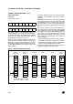
4.3 STRUCTURAL ORGANISATION
The FLASH program memory is organised in a
single 8-bit wide memory block which can be used
for storing both code and data constants.
The FLASH program memory is mapped in the up-
per part of the ST7 addressing space and includes
the reset and interrupt user vector area .
4.4 IN-SITU PROGRAMMING (ISP) MODE
The FLASH program memory can be programmed
using Remote ISP mode. This ISP mode allows
the contents of the ST7 program memory to be up
-
dated using a standard ST7 programming tools af-
ter the device is mounted on the application board.
This feature can be implemented with a minimum
number of added components and board area im
-
pact.
An example Remote ISP hardware interface to the
standard ST7 programming tool is described be
-
low. For more details on ISP programming, refer to
the ST7 Programming Specification.
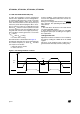
Remote ISP Overview
The Remote ISP mode is initiated by a specific se-
quence on the dedicated ISPSEL pin.
The Remote ISP is performed in three steps:
– Selection of the RAM execution mode
– Download of Remote ISP code in RAM
– Execution of Remote ISP code in RAM to pro-
gram the user program into the FLASH
Remote ISP hardware configuration
In Remote ISP mode, the ST7 has to be supplied
with power (V
DD
and V
SS
) and a clock signal (os-
cillator and application crystal circuit for example).
This mode needs five signals (plus the V
DD
signal
if necessary) to be connected to the programming
tool. This signals are:
– RESET: device reset
–V
SS
: device ground power supply
– ISPCLK: ISP output serial clock pin
– ISPDATA: ISP input serial data pin
– ISPSEL: Remote ISP mode selection. This pin
must be connected to V
SS
on the application
board through a pull-down resistor.
If any of these pins are used for other purposes on
the application, a serial resistor has to be imple
-
mented to avoid a conflict if the other device forces
the signal level.
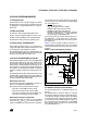
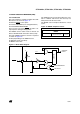
Figure 5 shows a typical hardware interface to a
standard ST7 programming tool. For more details
on the pin locations, refer to the device pinout de
-
scription.
Figure 5. Typical Remote ISP Interface
4.5 MEMORY READ-OUT PROTECTION
The read-out protection is enabled through an op-
tion bit.
For FLASH devices, when this option is selected,
the program and data stored in the FLASH memo
-
ry are protected against read-out piracy (including
a re-write protection). When this protection option
is removed the entire FLASH program memory is
first automatically erased. However, the E
2
PROM
data memory (when available) can be protected
only with ROM devices.
ISPSEL
V
SS
RESET
ISPCLK
ISPDATA
OSC1
OSC2
V
DD
ST7
HE10 CONNECTOR TYPE
TO PROGRAMMING TOOL
10KΩ
C
L0
C
L1
APPLICATION
47KΩ
1
XTAL