
Specifications


ST72104Gx, ST72215Gx, ST72216Gx, ST72254Gx
39/141
11 ON-CHIP PERIPHERALS
11.1 WATCHDOG TIMER (WDG)
11.1.1 Introduction
The Watchdog timer is used to detect the occur-
rence of a software fault, usually generated by ex-
ternal interference or by unforeseen logical condi-
tions, which causes the application program to
abandon its normal sequence. The Watchdog cir
-
cuit generates an MCU reset on expiry of a pro-
grammed time period, unless the program refresh-
es the counter’s contents before the T6 bit be-
comes cleared.
11.1.2 Main Features
■ Programmable timer (64 increments of 12288
CPU cycles)
■ Programmable reset
■ Reset (if watchdog activated) when the T6 bit
reaches zero
■ Optional reset on HALT instruction
(configurable by option byte)
■ Hardware Watchdog selectable by option byte.
11.1.3 Functional Description
The counter value stored in the CR register (bits
T6:T0), is decremented every 12,288 machine cy
-
cles, and the length of the timeout period can be
programmed by the user in 64 increments.
If the watchdog is activated (the WDGA bit is set)
and when the 7-bit timer (bits T6:T0) rolls over
from 40h to 3Fh (T6 becomes cleared), it initiates
a reset cycle pulling low the reset pin for typically
500ns.
The application program must write in the CR reg-
ister at regular intervals during normal operation to
prevent an MCU reset. The value to be stored in
the CR register must be between FFh and C0h
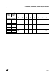
(see
Table 11 . Watchdog Timing (fCPU = 8
MHz)):
– The WDGA bit is set (watchdog enabled)
– The T6 bit is set to prevent generating an imme-
diate reset
– The T5:T0 bits contain the number of increments
which represents the time delay before the
watchdog produces a reset.
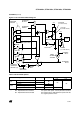
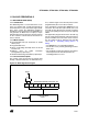
Figure 25. Watchdog Block Diagram
RESET
WDGA
7-BIT DOWNCOUNTER
f
CPU
T6
T0
CLOCK DIVIDER
WATCHDOG CONTROL REGISTER (CR)
÷12288
T1
T2
T3
T4
T5