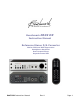
Benchmark DAC2 DX Instruction Manual Reference Stereo D/A Converter Native PCM and DSD Conversion Headphone Amplifier Dual Output Buses Asynchronous USB DAC2 DX Instruction Manual Rev A Page 1
Safety Information Fuses CAUTION: FOR CONTINUED FIRE HAZARD PROTECTION ALWAYS REPLACE THE FUSES WITH THE CORRECT SIZE AND TYPE (0.5A 250 V SLO-BLO® 5 X 20 MM – LITTELFUSE® HXP218.500 OR EQUIVALENT). THE FUSE DRAWER INCLUDES TWO FUSES. ALWAYS REPLACE BOTH FUSES AT THE SAME TIME. Voltage Selection THE DAC2 IS EQUIPPED WITH A UNIVERSAL POWER SUPPLY. THERE IS NO VOLTAGE SELECTION SWITCH. AC VOLTAGE RANGE IS 88-264 VAC, 50-60 HZ.
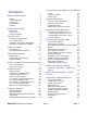
Contents Safety Information AC Power-Entry and Fuse Module24 2 Fuses Voltage Selection Power Cord Modifications Repairs 2 2 2 2 2 Quick Start Guide 5 Rear Panel Front Panel Control Functions 5 6 8 Applications Professional Applications HI-FI Applications Computer Sound Card Elimination Standalone Headphone Amplifier DAC2 vs.
Regulatory Compliance FCC and RoHS Compliance Statements FCC Notice (U.S.
Quick Start Guide Rear Panel Analog Audio Outputs The DAC2 DX has three stereo analog outputs driven from two separate output busses. By default both busses are controlled from the front panel volume control. Either or both busses may be programmed to BYPASS the volume control. When an output bus is set to BYPASS, the output level is set to a calibrated maximum level. The XLR outputs can deliver +24 dBu. The RCA outputs can deliver 2 Vrms (8.2 dBu).
Front Panel Power Switch Press once to turn on. Press once to turn off. IR Receiver The IR receiver for the remote control is located directly above the power switch. Do not block this opening. MUTE Switch and Light Press to MUTE all outputs. Press again to release. DIM Switch and Light Press to reduce the level of all outputs by 20 dB. Press again to release. Input Selector Switches and Lights Press the INPUT buttons to select a digital input.
Output Calibration Lights If a CALIBRATION light is on, the corresponding output bus is set to the calibrated maximum output level and the volume control is bypassed (BYPASS mode). If a CALIBRATION light is flashing slowly, the corresponding output bus is set to BYPASS mode, but the output is muted or dimmed.
Control Functions All DAC2 DX functions can be controlled from the IR remote control or from the front panel. In most cases, operation is identical (see table to the right for a summary of front panel and remote control functions). OFF (remote only) ON (remote only) POWER (front panel only) VOLUME U/D Press once to turn the unit off. * Press and hold to turn off all devices connected to the 12V TRIGGER. Press once to turn the unit on. * If the unit is already on, pressing ON will cancel MUTE and DIM.
Applications The DAC2 DX is a professional reference-grade digital to analog converter with two independent analog output busses. It includes Benchmark's reference-quality HPA2™ headphone amplifier, Benchmark's hybrid gain control system, and Benchmark's UltraLock2™ jitter attenuation system. The DAC2 DX is designed to connect directly to power amplifiers and powered monitors. It is also capable of delivering +24 dBu studio interface levels.
DAC2 vs. DAC1 The DAC2 series builds upon Benchmark’s highly successful DAC1 product family. Every DAC1 subsystem has been redesigned and upgraded to achieve higher performance. The DAC2 includes an updated version of Benchmark's highly-effective UltraLock™ jitter-attenuation system. New Features The DAC2 series introduced new features that add improve the listening experience while extending the versatility of the product.
DAC2 DX Features Feature List HGC™ (Hybrid Gain Control) – combines a motor-driven rotary control and a 32-bit digital attenuator with passive analog attenuators, to achieve state-of-the-art performance SABRE ES9018 - 32-bit PCM D/A conversion system, multiple 32-bit D/A converters per channel SABRE ES9018 – Native DSD D/A conversion system, multiple 1-bit DSD D/A converters per channel HPA2™ reference-grade headphone amplifier - “0-Ohm” high-current high-power outputs Dual Headphone Outp
Special DAC2 DX Features The DAC2 DX has some special features that set the DAC2 DX apart from the rest of the DAC2 product family: AES XLR digital input Dual Analog Output Busses Relay-Muted Analog Outputs These features are tailored to the needs of professional users but some Hi-Fi users may also find them useful. AES XLR Digital Input Many professional users have requested an AES XLR digital input. We have added this to the DAC2 DX without removing any of the other digital outputs.
Feature Details UltraLock2™ Clock System UltraLock2™ provides the outstanding jitter attenuation of the older UltraLock™ system while providing a higher SNR. High-Headroom Digital Processing All digital processing includes at least 3.5 dB headroom above an input level of 0 dBFS. This unique and important feature prevents all clipping in the digital processing, and provides clean, smooth, and transparent audio reproduction. Most competing products lack this important feature.
feel, and convenience of an analog control while providing the accuracy, transparency, and precision of 32-bit digital control. MUTE Function The MUTE function mutes all analog outputs. The MUTE function does not mute the DIGITAL PASS-THROUGH. DIM Function The DIM function fades all analog outputs to a level that is 20 dB lower than normal. This feature is intended to provide a convenient means to fade to and from a temporary background level without changing the volume control setting.
always provides the cleanest and shortest path from the digital source to the monitor outputs. This direct connection often produces a substantial improvement in sound quality. The DAC2’s XLR output is equipped with 0, 10 and 20 dB output attenuators for optimal interfacing. The pads optimize the output signal level of the DAC2 to the input sensitivity of virtually any amplifier. Most power amplifiers and powered monitors require the 10 dB or 20 pad setting.
DAC1 and DAC2 Product History The pristine audio performance of the award-winning DAC1 made it the ‘Benchmark’ of stand-alone D/A converters. The DAC1 USB and DAC1 PRE, and DAC1 HDR added features and minor performance improvements. DAC1 Series History The classic DAC1 was the first member of the Benchmark DAC1 family.
DAC2 Series History The DAC2 series represents a complete redesign of the DAC1. Our goal was to improve every aspect of the DAC1 while adding many of the most requested features.
Digital Inputs There are six stereo digital audio connectors on the DAC2 DX: USB - USB Audio 1.1 or 2.0 Input D1 - TOSLINK Optical Input D2 - TOSLINK Optical Input D3 - XLR Input D4 - Coaxial Input D5 - Coaxial Input or Output Input Formats The optical, XLR, and coaxial inputs can decode AES/EBU or S/PDIF PCM input signals. Professional or consumer data formats are automatically recognized. The USB, XLR and Coaxial inputs can also decode DSD when transmitted in DoP 1.1 format.
USB - Computer Input The USB input supports 44.1, 48, 88.2, 96, 176.4, and 192 kHz sample rates at word lengths up to 24-bits. The USB also accepts DSD. Mac operating systems support all sample rates and formats without drivers. Windows operating systems require drivers for DSD and PCM sample rates above 96 kHz. The USB input accepts a male ‘B-type’ male USB connector. An ‘A-B type’ USB cable is provided with the DAC2.
The DAC2’s USB AUDIO 1.1 MODE provides driverless operation with Windows XP/Vista/7/8, Mac OS X, and many Linux operating systems. USB AUDIO 2.0 MODE The DAC2’s USB AUDIO 2.0 MODE provides driverless operation with Mac OS X. It is compatible with Windows XP/Vista/7/8 if the Benchmark driver is installed. It has been tested on Mac OS X versions 10.6, 10.7, and 10.8. For the up-to-date information about more recent operating systems and suggestions for optimization, go to: http://benchmarkmedia.
The Coax inputs are DC isolated, current limited, and diode protected. The RCA body is bonded directly to the chassis to prevent currents in the internal ground system. This direct bonding also maximizes RF shielding. TIP: Shielded 75-Ohm coaxial cable is required for stable performance. Do not use 50Ohm cables or twisted pair cables, or any non-coaxial cables. The Coaxial inputs accept AES/EBU or S/PDIF digital audio formats.
Analog Outputs The DAC2 DX has two independent stereo output busses. By default, both busses are controlled by the front panel volume control. Either or both busses can be set to bypass the volume control. When the volume control is bypassed the volume is set to a calibrated maximum level. The DAC2 DX features high-current output drivers that are capable of driving 300-Ohm loads without an increase in distortion. They are also well suited for driving long cables or highcapacitance loads.
XLR Wiring The DAC2 uses industry-standard XLR wiring: XLR pin 2 = + Audio Out XLR pin 3 = - Audio Out XLR pin 1 = Cable Shield CAUTION: If the balanced XLR outputs are wired to an unbalanced input (using a special adapter cable), pin 3 must be left floating. Shorting pin 3 to ground will increase the temperature of the output drivers, will increase power consumption, and may cause distortion. Unbalanced Analog RCA Line Outputs The Left and Right unbalanced outputs use standard RCA style jacks.
AC Power-Entry and Fuses Fuses CAUTION: FOR CONTINUED FIRE HAZARD PROTECTION ALWAYS REPLACE THE FUSES WITH THE CORRECT SIZE AND TYPE (0.5A 250 V SLO-BLO® 5 X 20 MM – LITTELFUSE® HXP218.500 OR EQUIVALENT). THE FUSE DRAWER INCLUDES TWO FUSES. ALWAYS REPLACE BOTH FUSES AT THE SAME TIME. Voltage Selection THE DAC2 IS EQUIPPED WITH A UNIVERSAL POWER SUPPLY. THERE IS NO VOLTAGE SELECTION SWITCH. AC VOLTAGE RANGE IS 88-264 VAC, 50-60 HZ.
Internal Settings Jumper-Configured Options The following functions are jumper configured: XLR Output Pads Headphone Switches Headphone Gain Digital Pass-Through Removing Top Cover The DAC2 top cover must be removed to gain access to the jumpers. Do not attempt to remove the faceplate or the rear panel. CAUTION: The DAC2 contains static sensitive components. Static discharge may cause component failures, may affect the long-term reliability, or may degrade the audio performance.
XLR Output Pads The XLR outputs are equipped with low-impedance passive pads that may be used to reduce the output levels while preserving the full dynamic range of the DAC2 DX. The unit ships with the pads disabled (0 dB setting). When the output pads are enabled, the output impedance changes slightly, and the maximum allowable cable length should be reduced as shown in Table 1 (assuming 32 pF/foot and a maximum allowable loss of 0.1 dB at 20 kHz).
Headphone Switch Configuration: The DAC2 is configured so that the MAIN analog outputs will mute when a headphone plug is inserted into the left-hand jack. This is convenient when the user wishes to switch between headphones and speakers. This feature can be changed or defeated by moving jumpers at P1 on the back of the front panel. Either headphone switch can be enable or disabled by moving the jumpers.
Headphone Attenuation Jumpers (JP3 and JP4): The gain range of the HPA2™ can be set using jumpers JP3 and JP4: 0 dB attenuation - see Figure 3 10 dB attenuation - see Figure 4 (Factory Default) 20 dB attenuation - see Figure 5 The attenuation is inserted before the HPA2™ headphone amplifier. This attenuator location keeps the output impedance of the HPA2™ constant and very near 0 Ohms.
Figure 4 - 10 dB Headphone Attenuation - (Factory default) Figure 5 - 20 dB Headphone Attenuation DAC2 DX Instruction Manual Rev A Page 29
Digital Pass-Through Function Coaxial connector D5 is factory configured as an input. This connector can be reconfigured as a digital output by moving both P14 jumpers toward the faceplate. When re-configured as an output, the raw data from any selected digital input is buffered passed out through D5. The Digital Pass-Through is bit-transparent. No data is modified. MUTE, DIM, and VOLUME control functions do not change the data in any way.
Rack Mounting Options Call us, visit our website (http://www.BenchmarkMedia.com), or contact your dealer to purchase accessories for your DAC2. Universal Rack Adapter Tray The Universal Rack Adapter Tray is a tray that mounts up to two ½-wide Benchmark products in a standard 19 inch wide 1-RU rack space. The tray accepts any combination of ½-wide Benchmark products (with or without rack-mount type faceplates).
Benchmark Technologies Hybrid Gain Control™ "HGC" is Benchmark's unique Hybrid Gain Control™ system. The DAC2 combines active analog gain control, passive lowimpedance attenuators, a 32-bit digital gain control, and a servo-driven volume control. All inputs are controlled by the rotary volume control. This volume control moves in response to commands from the remote control. Analog inputs are never converted to digital, and digital inputs never pass through an analog potentiometer.
The USB sub-system remains active when the DAC2 is powered down. This prevents interruptions to the computer playback operations and eliminates the need to reconfigure the computer every time the converter is turned on. Jitter-Immune UltraLock2™ UltraLock2™ is an improved version of the UltraLock™ system used in the DAC1 product family. DSP processing is 32-bits, DSP headroom is 3.
HPA2™ Headphone Amplifier The DAC2 headphone output is driven by Benchmark’s signature HPA2™ headphone amplifier. This high-current, high-output amplifier has an output impedance of near 0Ohms. It is designed to drive loads as low as 30 Ohms without any increase in distortion. It also has sufficient amplitude to drive lowsensitivity 600-Ohm headphones. The HPA2™ includes current-limiting circuits that fully protect against damage from short circuits.
Fortunately, interface jitter has absolutely no effect on the audio unless it influences the conversion clock in an analog-to-digital converter (A/D) or in a digital-to-analog converter (D/A). Many converters use a single-stage Phase Lock Loop (PLL) circuit to derive their conversion clocks from AES/EBU, Wordclock, or Superclock reference signals. Single-stage PLL circuits provide some jitter attenuation above 5 kHz but none below 5 kHz.
can add a low and mid frequency ‘muddiness’ that was not in the original audio. Put UltraLock™ converters to the test: Jitter induced sidebands can be measured using an FFT analyzer. We encourage our customers to perform the above tests on UltraLock2™ converters (or let your ears be the judge). There will be absolutely no change in performance as jitter is added to any digital input on an UltraLock2™ converter. Try the same tests on any converter using conventional single or two-stage PLL circuits.
What UltraLock™ converters cannot do: UltraLock2™ converters cannot undo damage that has already been done. If an A/D with a jitter problem was used to create a digital audio signal, then there is nothing that can be done to remove the damage. Jitterinduced sidebands are extremely complex and cannot be removed with any existing audio DAC2 DX Instruction Manual device. Therefore, it is very important to attack jitter at both ends of the audio chain.
USB Audio System Setup Plug it in and Start Listening… Immediately Benchmark's Advanced USB Audio technology is truly 'Plug and Play'. When connecting to a USB port on a computer running Windows or Mac OSX, the computer will automatically and instantaneously recognize the presence of the Benchmark USB device in USB 1.1, playing tracks up to 96 kHz 24-bit. Any audio played from the computer will then be routed to the Benchmark USB device immediately. There is no software to install or configure.
USB Driver Installation - Windows XP, Vista, 7 Note: The DAC2 driver is available for download at: http://www.benchmarkmedia.com/dac/dac2hgc/driver Before you install the driver, make sure the USB is unplugged before installation of the driver. 1. In the DAC2 Driver folder, double click “setup.exe.
2. A welcome screen will pop-up. Click “Next.
3. When you see the following screen, turn on the DAC2, and select USB as your input. By default, the DAC2 is shipped in USB 1.0 mode. You can enable your DAC2 in USB 2.0 mode in two ways. 1) Using your remote control, hold down the USB button on your remote control for 3-4 seconds until you see the 4X LED light up for 3-4 seconds. 2) From the front faceplate, hold down both input buttons until you see the 4X LED light up for 3-4 seconds. 4.
Press “Install” DAC2 DX Instruction Manual Rev A Page 42
5. When the installation begins you will see the following screen. Please be patient while the driver installs. Installation time is between 1-5 minutes. 6. Once the installation finishes a message at the top will say “Installation Complete.” Press “Next” to continue.
7. Click “Finish.” The Setup will close automatically and this completes the installation process. You can now enjoy music up to 192 kHz and DSD.
Performance Graphs - DAC2 Series The following graphs were produced using a DAC2 HGC. The DAC2 DX provides similar performance. Audio Precision FFT Idle Channel Noise, 0 dBr = 0 dBFS = 23 dBu +0 +0 -20 -20 -40 -40 -60 -60 d B r -80 -80 d B r A -100 -100 A -120 -120 -140 -140 -160 -160 0 2k 4k 6k 8k 10k 12k 14k 16k 18k 20k 22k 24k 26k 28k 30k 32k Hz Sweep Trace Color Line Style Thick Data Axis 1 1 1 2 Green Red Solid Solid 4 4 Fft.Ch.1 Ampl Fft.Ch.
Audio Precision FFT Idle Channel Noise - Low Frequency, 0 dBr = 0 dBFS = 23 dBu dx=120.470 Hz +0 dy=-1.126 dB +0 -20 -20 -40 -40 -60 -60 d B r -80 -80 d B r A -100 -100 A -120 -120 -140 -140 -156.413 -157.539 -160 -160 60.1566 75 50 25 100 125 150 180.626 175 200 225 250 275 300 325 350 375 400 Hz Sweep Trace Color Line Style Thick Data Axis 1 1 1 2 Green Red Solid Solid 4 4 Fft.Ch.1 Ampl Fft.Ch.2 Ampl Left Right Comment Cursor1 Cursor2 *-156.
Audio Precision DAC2 - FFT 10 kHz, 0 dBr = 0 dBFS = 23 dBu dx=10.0196 kHz +0 dy=-5.604 dB +0 -20 -20 -40 -40 -60 -60 d B r -80 -80 d B r A -100 -100 A -114.636 -120 -120.24 -120 -140 -140 -160 -160 0 2k 4k 6k 8k 10k 12k 14k 16k 18k 20.0391k 20k 22k 24k 26k 28k 30.0587k 30k 32k Hz Sweep Trace Color Line Style Thick Data Axis 1 1 1 2 Green Red Solid Solid 4 4 Fft.Ch.1 Ampl Fft.Ch.2 Ampl Left Right Comment Cursor1 Cursor2 *-114.636 dBr -116.
Audio Precision DAC2 - FFT 1 kHz, 0 dBr = 0 dBFS = 23 dBu dx=.995695 kHz +0 dy=-13.022 dB +0 -20 -20 -40 -40 -60 -60 d B r -80 -80 d B r A -100 -100 A -115.268 -120 -120 -128.29 -140 -140 -160 -160 0 200 400 600 800 1k 1.2k 1.4k 1.6k 1.8k 2.00391k 2k 2.2k 2.4k 2.6k 2.8k 2.99961k 3k 3.2k Hz Sweep Trace Color Line Style Thick Data Axis 1 1 1 2 Green Red Solid Solid 4 4 Fft.Ch.1 Ampl Fft.Ch.2 Ampl Left Right Comment Cursor1 Cursor2 *-115.268 dBr -115.
Audio Precision dx=40.4114 kHz +1 d B r DAC2 - FREQUENCY RESPONSE Fs = 96 kHz 10/24/12 16:02:03 dy=-0.011 dB +1 -0 -0 -0.009 -0.02 -1 -1 -2 -2 -3 -3 -4 -4 -5 -5 -6 -6 -7 -7 -8 -8 -9 -9 d B r A B -10 10.0021 5k 10k 15k 20k 25k 30k 35k 40.4214k 40k 45k -10 Hz Sweep Trace Color Line Style Thick Data Axis 1 1 1 2 Green Red Solid Solid 4 4 Anlr.Level A Anlr.Level B Left Right Comment Cursor1 Cursor2 -0.011 dBr A *-0.009 dBr -0.026 dBr A *-0.
Audio Precision DAC2 - Differential Phase Fs = 96 kHz dx=19.7956 kHz +1 dy=+0.23 deg +0.8 +0.6 +0.47 +0.4 +0.24 +0.2 d e g +0 -0.2 -0.4 -0.6 -0.8 -1 2.5k 5k 7.5k 10k 12.5k 15k 17.5k 20.2555k 20k 22.5k 25k 27.5k 30k 32.5k 35k 37.5k 40.0511k 40k 42.5k 45k Hz Sweep Trace Color Line Style Thick Data Axis 1 2 1 1 Green Red Solid Solid 4 4 Anlr.Phase Anlr.Phase Left Left Comment Cursor1 Cursor2 -0.09 deg *+0.24 deg -0.21 deg *+0.47 deg DAC2 - Differential Phase.
Audio Precision DAC2 - THD+N vs AMPLITUDE AT 1 KHZ (w/20 kHz LPF unweighted) Balanced Outputs, Relative to 0 dBFS, 0 dBFS = +23 dBu -96 -98 -100 -102 -104 d B r A -106 -108 -110 -112 -114 -116 -118 -120 -14 -13 -12 -11 -10 -9 -8 -7 -6 -5 -4 -3 -2 -1 -0 dBFS Sweep Trace Color Line Style Thick Data Axis 1 1 1 2 Green Red Solid Solid 4 4 Anlr.THD+N Ampl Anlr.THD+N Ampl Left Left Comment DAC2 - Balanced THD+N vs AMPLITUDE.at27 Graph Plot 7 - Balanced THD+N vs.
Audio Precision DAC2 - THD+N vs AMPLITUDE AT 1 KHZ (w/20 kHz LPF unweighted) Unbalanced Outputs, Relative to 0 dBFS, 0 dBFS = +7.2 dBu -95 -96 -97 -98 -99 -100 -101 -102 -103 -104 -105 d B r -106 A -109 -107 -108 -110 -111 -112 -113 -114 -115 -116 -117 -118 -119 -120 -14 -13 -12 -11 -10 -9 -8 -7 -6 -5 -4 -3 -2 -1 -0 dBFS Sweep Trace Color Line Style Thick Data Axis 1 1 1 2 Green Red Solid Solid 4 4 Anlr.THD+N Ampl Anlr.
Audio Precision DAC2 - THD+N vs AMPLITUDE AT 1 KHZ (w/20 kHz LPF unweighted) Headphone Outputs, Relative to 0 dBFS, 0 dBFS = +7.2 dBu -86 -88 -90 -92 d B r -94 -96 A -98 -100 -102 -104 -14 -13 -12 -11 -10 -9 -8 -7 -6 -5 -4 -3 -2 -1 -0 dBFS Sweep Trace Color Line Style Thick Data Axis 1 1 1 2 Green Red Solid Solid 4 4 Anlr.THD+N Ampl Anlr.THD+N Ampl Left Left Comment DAC2 - HEADPHONE - THD+N_VS_AMPLITUDE.
Audio Precision DAC2 - THD+N VS FREQ AT 0 dBFS (w/80 kHz LPF unweighted) Balanced Outputs -90 -92.5 -95 -97.5 d B -100 -102.5 -105 -107.5 -110 20 50 100 200 500 1k 2k 5k 10k 20k Hz DAC2 - THD+N vs FREQUENCY 80kHZ.at27 Graph Plot 10 - THD+N vs. FREQUENCY 80 kHz The analog output stages on the DAC2 have high slew rates and are capable of maintaining low THD levels at high frequencies even when driven to 0 dBFS.
Audio Precision dx=8.99682 kHz -90 d B DAC2 - THD VS FREQ AT 0 dBFS Balanced Outputs dy=+3.144 dB -90 -95 -95 -100 -100 -105 -105 -110 -110 -112.066 -115 -115.21 -115 -120 -120 -125 -125 -130 20 50 100 200 1.00318k 1k 500 2k 5k 10k 10k d B -130 Hz Sweep Trace Color Line Style Thick Data Axis 1 1 1 2 Green Red Solid Solid 4 4 Distortion.Ch.1 Harm Sum1 Ratio Distortion.Ch.1 Harm Sum2 Ratio Left Right Comment Cursor1 Cursor2 *-115.210 dB -115.165 dB *-112.
Audio Precision DAC2 - THD VS FREQ AT 0 dBFS - ALL OUTPUTS dx=8.99682 kHz -90 dy=+8.088 dB -90 -95 -95 -100 -100 -105 d B -105 -106.739 d -110 B -115 -114.827 -110 -115 -120 -120 -125 -125 -130 20 50 100 200 1.00318k 1k 500 2k 5k 10k 10k -130 Hz Sweep Trace Color Line Style Thick Data 1 1 2 2 3 3 2 3 2 3 2 3 Blue Cyan Red Magenta Green Yellow Solid Solid Solid Solid Solid Solid 4 4 4 4 4 4 Distortion.Ch.1 Harm Distortion.Ch.2 Harm Distortion.Ch.1 Harm Distortion.Ch.
Benchmark Media Systems, Inc. DAC2 - THD+N vs Sample Rate, 1 kHz at 0 dBFS (w/20 kHz LPF unweighted) Balanced Outputs -90 -92.5 -95 -97.5 -100 -102.5 d B -105 -107.5 -110 -112.5 -115 -117.5 -120 40k 60k 80k 100k 120k 140k 160k 180k 200k Hz Sweep Trace Color Line Style Thick Data Axis 1 1 1 2 Green Red Solid Solid 4 4 Anlr.THD+N Ratio Anlr.THD+N Ratio Left Left Comment DAC2 - THD+N vs Sample Rate.
Audio Precision DAC2 - INTERFACE JITTER TOLERANCE - Distortion vs Jitter 3.456 kHz Test Tone at 0 dBFS, THD+N 22 to 22 kHz BW +0 20 -10 10 -20 5 -30 2 -40 d B 1 -50 500m -60 U I 200m -70 100m -80 50m -90 20m -100 -110 100 200 500 1k 2k 5k 10k 20k 50k 90k 10m Hz Sweep Trace Color Line Style Thick Data Axis 1 1 1 2 Green Red Solid Solid 4 4 Anlr.THD+N Ratio Dio.Interface Jitter Left Right Comment DAC2 THD+N (22-22kHz) (Green Trace) vs.
Audio Precision DAC2 - INTERFACE JITTER TOLERANCE FFT 10 kHz Test Tone at 0 dBFS, AES Jitter Tolerance Sweep +0 -20 -40 d B r -60 -80 A -100 -120 Audio Precision d B r DAC2 - INTERFACE JITTER TOLERANCE FFT 10 kHz Test Tone at 0 dBFS, AES Jitter Tolerance Sweep -140 0 +00 Sweep Sweep 1 12 23 3 4 5 6 7 8 9 10 11 12 13 14 15 16 17 18 19 20 21 22 23 24 25 26 27 28 29 30 31 2k 4k 2k Trace Trace 2 22 22 2 2 2 2 2 2 2 2 2 2 2 2 2 2 2 2 2 2 2 2 2 2 2 2 2 2 2 2 2 Color Color Green Yellow Green Red Red
Audio Precision +0 dx=9.00196 kHz DAC2 - 11K 12K IMD 11/06/12 08:15:12 dy=-6.731 dB +0 -10 -10 -20 -20 -30 -30 -40 -40 -50 -50 -60 -60 d B r -70 -70 -80 -80 d B r A -90 -90 A -100 -100 -110 -110 -120 -122.154 -130 -128.885 -120 -140 -140 -150 -150 -160 0 -130 1.01761k 2k 4k 6k 8k 10.0196k 10k 12k 14k 16k 18k 20k -160 Hz DAC2 - IMD 11K 12K.at27 Graph Plot 16 - IMD 11k 12K This plot demonstrates that the DAC2 has very low IMD distortion.
Preliminary Specifications Audio Performance Fs = 44.1 to 96 kHz, 20 to 20 kHz BW, 1 kHz test tone, 0 dBFS = +24 dBu (unless noted) SNR – A-Weighted, 0 dBFS = +20 to +29 dBu 126 dB SNR – Unweighted, 0 dBFS = +20 to +29 dBu 123 dB THD+N, 1 kHz at 0 dBFS -109 dBFS, -109 dB, 0.00035% THD+N, 1 kHz at -1 dBFS -110 dBFS, -109 dB, 0.00035% THD+N, 1 kHz at –3 dBFS -113 dBFS, -109 dB, 0.00035% THD+N, 20 to 20 kHz test tone at –3 dBFS -112 dBFS, -108 dB, 0.00040% +0 dB, -0.
Audio Performance (continued) Maximum Lock Time after Fs change Soft Mute Ramp Up/Down Time Mute on Receive Error Mute on Lock Error Mute on Idle Channel 50/15 us De-Emphasis Enable De-Emphasis Method De-Emphasis Supported at 400 ms 50 ms Yes Yes No Automatic in Consumer Mode Digital IIR Fs = 32, 44.1, 48 kHz Group Delay (Latency) Delay – Digital Input to Analog Output (function of sample rate) 1.36 ms at 44.1 kHz 1.27 ms at 48 kHz 0.90 ms at 88.2 kHz 0.82 ms at 96 kHz 0.51 ms at 176.4 kHz 0.
Jitter Tolerance >12.75 UI sine, 100 Hz to 3 kHz (With no Measurable Change in Performance) >1.5 UI sine at 20 kHz >1.5 UI sine at 40 kHz >1.5 UI sine at 80 kHz >1.5 UI sine at 90 kHz >0.
Balanced Analog Outputs Number of Balanced Analog Outputs Output Connector Output Impedance 2 Gold-Pin Neutrik™ male XLR 60 Ohms (Attenuator off) 425 Ohms (Attenuator = 10 dB) Analog Output Clip Point Factory Set Bypass Level (at 0 dBFS) Output Level Range (at 0 dBFS) In ‘Variable’ Mode 135 Ohms (Attenuator = 20 dB) +30 dBu +24 dBu (Attenuator = 0 dB) Off to +24 dBu (Attenuator off) Off to +14 dBu (Attenuator = 10 dB) Output Level Variation with Sample Rate (44.1 kHz vs.
HPA2TM Headphone Outputs Number of Headphone Outputs Output Connectors Output Impedance Output Level Control Output Level Range (at 0 dBFS) into 60-Ohm Load Maximum Output Current Overload Protection (independent per channel) Bandwidth THD+N 2 ¼” TRS with switch on left-hand jack < 0.11 Ohms Stereo Control on Front Panel Off to +17 dBu 250 mA Current limited at 300 mA, Thermal > 500 kHz -106 dB, 0.0005% into 30 Ohms at +18 dBu (1.
AC Power Requirements Nominal Input Operating Voltage Range (VAC RMS) Frequency Power Fuses Min/Max Operating range (VAC RMS) 100 – 240V 50-60 Hz < 0.5 Watts Idle 12 Watts Typical Program 15 Watts Maximum 5 x 20 mm (2 required) 0.5 A 250 V Slo-Blo® Type 90 – 260 47 – 63Hz Dimensions Form Factor Depth behind front panel Overall depth including connectors but without power cord Width Height ½ Rack Wide, 1 RU High 8.5” (216 mm) 9.33” (237 mm) 9.5” (249 mm) 1.725” (44.
Regulatory Compliance FCC and RoHS Compliance Statements FCC Notice (U.S. Only) NOTICE: This equipment has been tested and found to comply with the limits for a Class B digital device, pursuant to Part 15 of the FCC Rules. These limits are designed to provide reasonable protection against harmful interference in a residential installation.
CE Certificates of Conformity DAC2 DX Instruction Manual Rev A Page 68
Warranty Information Benchmark 1 Year Warranty The Benchmark 1 Year Warranty Benchmark Media Systems, Inc. warrants its products to be free from defects in material and workmanship under normal use and service for a period of one (1) year from the date of delivery. This warranty extends only to the original purchaser. This warranty does not apply to fuses, lamps, batteries, or any products or parts that have been subjected to misuse, neglect, accident, modification, or abnormal operating conditions.
Benchmark Extended Warranty The Benchmark Extended 5* Year Warranty Benchmark Media Systems, Inc. optionally extends the standard one (1) year warranty to a period of five (5)* years from the date of delivery. *For the extended warranty to become effective, the original purchaser must register the product at the time of purchase either by way of the enclosed registration card or through the product registration section of the Benchmark Media Systems, Inc. website.
Copyright © 2007, 2008, 2009, 2012, 2014 Benchmark Media Systems, Inc. All rights reserved. Benchmark Media Systems, Inc. Benchmark Media Systems, Inc. 203 East Hampton Place, STE 2 Syracuse, NY 13206-1633 USA PHONE: +1-315-437-6300 FAX: +1-315-437-8119 www.benchmarkmedia.