Installation and Servicing Instructions Alpha InTec 26C, 30C, 34C and 24X, 28X Range of Wall Mounted, Fan Assisted, Room Sealed, Gas Fired, High Efficiency Condensing Combination Boilers For Technical help or for Service call ... ALPHA HELPLINE Tel: 0844 871 8764 website: www.alpha-innovation.co.uk Nepicar House, London Road, Wrotham Heath, Sevenoaks, Kent TN15 7RS Alpha InTec 24X (NG) Alpha InTec 28X (NG) Alpha InTec 26C (NG) Alpha InTec 30C (NG) Alpha InTec 34C (NG) G.C. No. 47 532 45 G.C. No.
BENCHMARK SCHEME To comply with Building Regulations Part L1 (Part 6 in Scotland) the boiler should be installed in accordance with the manufacturer’s instructions. Self-certification that the boiler has been installed to comply with Building Regulations can be demonstrated by completing and signing the Benchmark Checklist at the back of these instructions Code of Practice For the installation, commissioning and servicing of domestic heating and hot water products.
CONTENTS 1 2 3 4 5 6 Introduction.........................................3 Technical data....................................4 General boiler information..................8 Installation..........................................15 Commissioning...................................23 Routine servicing................................27 1 7 8 9 10 Component replacement....................30 Wiring diagrams.................................37 Error codes and fault finding..............39 Short parts list......
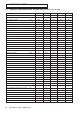
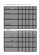
2 2.1 TECHNICAL DATA TECHNICAL PERFORMANCE DATA - NATURAL GAS (Cat I2H 2H - G20 20 mbar) InTec 26C InTec 30C InTec 34C InTec 24X InTec 28X Heat input gross - DHW kW 29.7 32.7 37.9 27.5 31.4 Heat input gross - CH kW 20.6 27.1 31.5 20.6 27.1 Heat input net - DHW kW 26.8 29.5 33.7 24.8 28.3 Heat input net - CH kW 18.6 24.4 28.0 18.6 24.4 Heat output condensing (50/30°C) - CH kW 20.0 26.3 30.7 20.0 26.8 Heat output non condensing (80/60°C) CH kW 18.0 23.6 27.6 18.
2.2 TECHNICAL PERFORMANCE DATA - PROPANE GAS (Cat I3P 3P - G31 - 37 mbar) InTec 26C InTec 30C InTec 34C InTec 24X InTec 28X Heat input gross - DHW kW 29.7 32.7 37.9 27.5 31.4 Heat input gross - CH kW 20.6 27.1 31.5 20.6 27.1 Heat input net - DHW kW 26.8 29.5 33.7 24.8 28.3 Heat input net - CH kW 18.6 24.4 28.0 18.6 24.4 Heat output condensing (50/30°C) - CH kW 20.0 26.3 30.7 20.0 26.8 Heat output non condensing (80/60°C) CH kW 18.0 23.6 27.6 18.0 23.
2.4 FLUE LENGTHS CD Easy-Flue 500 mm with terminal and 90° bend. A CD Easy-Flue 1000 mm with terminal and 90° bend is also available. CD 750 mm and 1000 mm flue extensions are available. Length of Flue Required:Rear Flue = wall thickness + 160 mm (includes terminal). This is without back frame, add 45 mm if the wall jig is used.
2.
3 3.1 GENERAL BOILER INFORMATION GAS SUPPLY The meter and supply pipes must be capable of delivering the required quantity of gas in addition to the demand from any other appliances in the house. Refer to Technical performance data in Section 2.1 and 2.2. The complete installation, including the meter, must be tested for gas tightness and purged as described in BS 6891. 3.2 ELECTRICAL SUPPLY The boiler requires a 230/240 V ~ 50 Hz mains supply, fused at 3 A The boiler must be earthed.
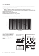
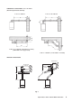
HORIZONTAL FLUE OPTIONS - Lmax = 12 metres (245 mm length includes terminal) L = B + C + 245 mm L = B + C + E + 245 mm B C B C E B F E C L = B + E + F + 245 mm + (90° bend = 1.3 metre) (add 45 mm to 'F' if a jig is used) B L = B + C + 245 mm + (2 x 45° bends = 1.8 metre) VERTICAL FLUE OPTIONS Not less than 300 mm Not less than 300 mm Not less than 300 mm Not less than 300 mm H H Hmax = 15 m Hmax = 13.2 m Fig.
3.5 FLUE TERMINAL LOCATION - Figs. 4 and 5 Q OP G J N D Boundary HI Fig. 4 Terminal position Min. distance (mm) A Directly below an opening, air brick, windows, etc.
Proximity of flue duct outlets to boundaries The flue duct shall be sited so that it is at least 600 mm (see Fig. 5) from the boundary line when facing it and at least 300 mm from the boundary line when running parallel to it.
3.7 CENTRAL HEATING SYSTEM - Fig. 6 The boiler is designed for use in a sealed central heating system in accordance with the requirements of BS EN 12828 and BS 6798. The system should be designed to operate with flow temperatures of up to 82°C. When designing the system, the pump head, expansion vessel size, mean radiator temperature, etc. must all be taken into account. Refer to the pump performance table for guidelines.
3.9 FLUSHING THE HEATING SYSTEM It is essential that the central heating system is thoroughly cleaned and flushed when fitting an Alpha InTec boiler. Failure to do so will invalidate the warranty. The primary condensing heat exchanger is constructed in stainless steel and therefore is compatible with most materials used in a heating system. If a cleaning agent and inhibitor are used, they must be applied in accordance with their manufacturers instructions.
Use waterproof pipework insulation in very exposed positions Plastic pipe Ensure pipe is adequately supported Open end of pipe diverted into gully below grid but above water level Minimum gradient 2½° Fig. 8 - External gully 22mm termination from boiler, increase to 32 mm if external Cement mortar sealing 500 mm min.
4 4.1 1. INSTALLATION UNPACKING The boxes required when the boiler is installed with a horizontal flue are as follows:- Box 1 ����������������������������� Cased boiler fitted with water and gas valves, union bends and washers Mounting bracket plus screws and wall plugs Condensate discharge pipe Literature pack and Wall template Box 2 ���������������������������������CD Easy-Flue 500 mm or CD Easy-Flue 1000 mm.
4. Cut the 110 mm diameter hole (or use a 107 mm core drill) in the wall for the flue. Notes: 1. Ensure the hole is horizontal. 2. For internal fitting of the flue, using the flue sealing collar supplied, cut a 130 mm dia. flue hole using a 127 mm core drill. 5. Drill the fixing holes (10 mm dia.) to accept the No.10 plugs supplied. Using the screws supplied, fit the mounting bracket or wall jig if used. If applicable drill a 22 mm dia.
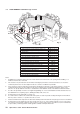
Seasonality valve Filling loop taps Cold water inlet filter Filling loop Condensate trap Condensate discharge pipe 65 70 C 37 95 B D 58 F 70 Heating return valves Heating flow valve Heating flow valve Heating drain point Heating drain point Cyclone drain point Cyclone drain point Wall jig Wall jig 45 23 20 65 A E 70 C 37 95 B C models D 58 F 70 45 A E X models C - Gas inlet (22 mm) D - Cold water mains inlet (15 mm) A - Heating flow (22 mm) B - Hot water outlet (15 mm) C
Check collar is sealing the wall and it is not restricting any openings of the flue terminal 130 mm Fig. 17 - Fitting the flue from inside 5. Position the smaller Easy-Flue 40 mm clamp (with seal) supplied, over the bend. Fit the bend to the boiler and rotate to the correct position. Secure in position using the clamp. Ensure the clamp is located centrally over both the bend and boiler adaptor. 6. Fit the inside (white) flue sealing collar over the Easy-Flue.
4.8 EXTENDING THE FLUE - Fig. 20 Note: The flue assembly length must not exceed the maximum length stated, including the equivalent lengths of any extensions, bends etc. used for plume management components. InTec boilers must not exceed the maximum of an equivalent horizontal flue length of 12 m. 1. When the flue length required is more than the maximum stated in Section 4.6, paragraph 1, refer to the table below and Figs 14 and 15.
10. Secure the flue assembly to the bend with the clamp ensuring it is positioned centrally over the joint, ensuring the 'TOP' marked on the outer duct is positioned at the top. Note: Check the flue terminal protrudes 120 mm out of the wall and that the inner duct of the terminal is positioned correctly, i.e. the inner duct within the terminal is at the top. See Fig. 20. 11.
Terminal end section from CD Easy-Flue Terminal end section from CD Easy-Flue Note: 1. Ensure each joint is secured with the screw supplied. Min. 400 mm 2. Ensure there is always a slight slope towards the CD Easy-Flue so that there is no part of the pipework where condensate will collect. C Terminal end section from CD Easy-Flue C PM length = C + (2 x 93° bend = 2.6 m) + (2 x 45° bends = 1.
4.10 CONNECT THE MAINS SUPPLY - Fig. 23 1. Gain access to the boiler terminal block by releasing the two fixing screws (one each side) securing the control panel and lowering the panel. Refer to Technical Data, Section 2.6 for connection details. Terminal block cover 2. Note: This boiler has been fitted with a mains supply cable.
5 COMMISSIONING When commissioning the boiler, ensure the Benchmark Checklist at the back of these instructions is completed. 5.1 FILL THE SYSTEM 1. The boiler is fitted with an automatic air vent positioned on the pump (see Fig. 34), ensure that the vent is always open. 2. Open the central heating flow and return valves (vertical slot in-line with valve) (see Fig. 13). 3. Open the fill point valves on the filling loop until water is heard to flow. 4.
5.4 INITIAL LIGHTING - Refer to Fig. 25 1. Before turning on the gas and electrical supplies check the heating system is filled to the correct pressure. Refer to Section 5.1 Fill the System. The pressure gauge on the right of the control panel indicates the heating system pressure. When the boiler is cold the needle should be within the green band. 2. With the gas and electrical supplies to the boiler off, ensure that the mains water inlet valve and the central heating flow and return valves are open.
Frost Thermostat The boiler incorporates a built in frost thermostat which automatically turns on the boiler and pump if the water in the boiler falls below 4°C, providing the electrical supply is on and the boiler is in standby mode. The boiler will operate until the water temperature in the boiler reaches 42°C. Any other pipework outside of the boiler must be protected from the risk of freezing and insulated.
5.8 1. 2. 3. 4. 5. 5.9 FINAL ASSEMBLY Raise the control panel and secure in position with the screws provided. Note: If the wall jig is used, fit the bottom tray over the base of the boiler. If the boiler is to be left in service with the User, set the controls, clock (if fitted, see User's Operating manual) and room thermostat (if fitted) to the User's requirements. If the boiler is not to be handed over immediately, close the boiler gas service cock and switch off the electrical supply.
6 ROUTINE SERVICING To ensure efficient operation of the boiler it is recommended that it is checked and serviced as necessary at regular intervals. The frequency of servicing will depend upon the particular installation conditions and usage, but in general once per year should be adequate. It is the law that any service work must be carried out by a competent person, i.e. Gas Safe registered personnel.
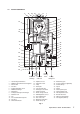
Front case locating pins Four nuts and washers and Manual air vent four screws securing combustion chamber front assembly Combustion chamber front assembly Flame sensing electrode Expansion vessel test/fill point Gas pipe union Flue gas sampling point Viewing window Air supply pipe Air supply pipe fixing screw Ignition generator Fan assembly Pressure tube connections Air supply pipe fixing screw Fan assembly fixing screws Front case fixing screws Fig. 28 6.2 PREPARE FOR SERVICING - Fig. 28 1.
Burner Front panel insulation Burner to electrode gap 6 mm Combustion chamber front assembly Flame sensing electrode Electrode gap 3 - 4 mm Ignition electrodes Fig. 29 6.4 1. RE-ASSEMBLE THE BOILER Replace the burner, ensuring it is located correctly and secure it in position using the four screws previously removed. Important: Before replacing the combustion chamber front assembly, pour at least 200 cc of water into the coils of the heat exchanger.
7 COMPONENT REPLACEMENT It is the law that any service work must be carried out by a competent person, i.e. Gas Safe registered personnel. Warning: Before replacing any boiler components, isolate the electrical supply and close the boiler gas service cock. Allow the boiler to cool. Always test for gas tightness after replacing any gas carrying components or disturbing any gas connections. Always carry out electrical system checks i.e.
7.6 FAN - Fig. 28 1. Gain access behind the room sealed chamber as described in Section 7.1. 2. Remove the two screws securing the air supply pipe (see Fig. 28) and remove the pipe. 3. Unplug the fan plug and remove the two screws securing the fan to the combustion chamber front (see Fig. 28). 4. Withdraw the fan to the right of the boiler - this can be made easier if the right hand side panel is removed. 5. Remove the air inlet elbow from the old fan and fit it to the new one. 6.
7.10 GAS VALVE - Fig. 30 Note: The replacement of the gas valve or PCB must be carried out by a Gas Safe registered engineer with the use of a flue analyser. 1. Gain access behind the front casing as in Section 7.1. 2. Disconnect the positive pressure tube from the gas valve. 3. Disconnect the electrical plug. 4. Disconnect the burner manifold pipe union and the gas inlet pipe union. 5. Remove the two screws from beneath the boiler and lift out the valve assembly. 6.
7.14 ALPHA CONTROLS (if fitted) - Fig. 24 Note: For replacement only use an Alpha single channel control. Do not fit a two channel control. 1. Gain access behind the control panel as described in Section 7.1. 2. Remove the three screws securing the terminal block cover at the rear of the panel. 3. Disconnect the wiring from the control. 4. Remove the three control retaining screws and withdraw the control from the panel. 5.
7.20 DHW FLOW SWITCH - Fig. 32 1. Gain access behind the front casing as described in Section 7.1. 2. Isolate the mains water supply and open all hot taps to drain any water from the boiler. 3. Disconnect the wires from the switch. 4. Undo the union nut and remove the fixing screw from the bottom of the switch. 5. Remove the two 4 mm socket head capscrews securing the top switch and lift out the switch. 6. Fit the new switch and re-assemble in reverse order. 7.21 PRIMARY HEAT EXCHANGER - Figs.
7.23 PRIMARY TEMPERATURE SENSOR - Fig. 30 1. Gain access as described in Section 7.1 and drain the heating circuit described in Section 7.2. 2. Disconnect the wiring and unscrew the sensor. Re-assemble in reverse order with a new sensor and sealing washer. 3. Refill and pressurise the system. (Refer to Commissioning, Section 5.1). 7.24 AUTOMATIC AIR VENT - Fig. 34 1. Gain access behind the front casing and drain the boiler heating circuit as described in Sections 7.1 and 7.2. 2.
7.29 MAINS WATER INLET FILTER - Fig. 13 1. The mains water inlet filter is located in the body of the DHW flow switch. Refer to Section 7.17 to remove the flow switch. 2. The filter can be removed using a small screwdriver. 3. Clean the filter and re-assemble in reverse order. 7.30 DIVERTER VALVE CARTRIDGE - Fig. 32 1. Gain access behind the front casing and drain the boiler heating circuit as described in Sections 7.1 and 7.2. 2. Remove the diverter valve motor as described in Section 7.13. 3.
8 WIRING DIAGRAMS ILLUSTRATED WIRING DIAGRAM Low voltage electrical connections 230 V electrical connections Supply 230 V ~ 50 Hz Diverter DHW Valve Bl Br Br Bl L N G/Y R Bl Bk Spark Generator Br - X20 R Br Gy Relay Board X26 (optional) 50 51 52 53 54 55 56 8 9 10 11 12 13 G G W W Bk Bk Bl Bl Br Bl Bk Bl R Br Br Gy Br Remove link R Br to connect G/Y Alpha controls 1 2 3 4 L N 3 4 B A X3 Fuse 3.
8.2 FUNCTIONAL FLOW WIRING DIAGRAM N X3 N Fuse 3.15 AF (on PCB) 230/240V ~ 50Hz Fuse 3A L X3 L X3 4 1 2 2 Alpha Control (Optional) 3 4 Remove link to connect external control N 1 X3 3 Pump Diverter Valve Motor Spark Generator X16 1 N X16 3 N X9 2 N External Sensor (optional) BUS Flame Sensing Electrode Climatic Control (low voltage) (optional) DHW Sensor DHW Flow Switch System Pressure Switch Overheat Thermostat Heat Exchanger Thermal Fuse 1 2 3 4 L N 3 4 B A X3 Fuse 3.
9 9.1 ERROR CODES AND FAULT FINDING CARRY OUT INITIAL FAULT FINDING CHECKS 1. Check that gas, electrical and water supplies are available at the boiler. i.e. Inlet gas pressure = 20 mbar - Electrical supply = 230/240 V ~ 50 Hz CH water system pressurised to between 0.75 and 1.25 bar - DHW flow rate is more than 2.5 litre/min 2. Carry out electrical system checks, i.e. Earth Continuity, Resistance to Earth, Short Circuit and Polarity with a suitable meter.
Error code 40 Fault Fault description Possible causes 20 Flame sensing fault False flame detection Flame detected but gas valve is not open Check flame sensing electrode and lead PCB fault 24 Control panel button fault Control panel button stuck in the on position Check for jammed control panel buttons Check for jammed PCB buttons 25 Overheat lock out Rapid temperature rise of flue sensor Air in heat exchanger Blocked or restricted primary flow Heat exchanger air flow blocked Flue restrictio
10 SHORT PARTS LIST Reference Description Qty. Alpha Pt. No. Spark generator 1 1.018162 Diverter valve cartridge assembly 1 3.020380 Seasonality valve 1 3.017106 12 L flow regulator (red - 24X) 1 1.020412 Pressure gauge 1 1.023551 Condensate trap assembly 1 3.017281 Flue sensor 1 1.024296 DHW sensor 1 1.025380 Overheat thermostat 1 1.025797 Flame sensing electrode 1 1.032007 Inlet mesh filter 1 1.8403 Flue turret (30C - 34C - 28X) 1 1.
GAS BOILER SYSTEM COMMISSIONING CHECKLIST This Commissioning Checklist is to be completed in full by the competent person who commissioned the boiler as a means of demonstrating compliance with the appropriate Building Regulations and then handed to the customer to keep for future reference. Failure to install and commission according to the manufacturer’s instructions and complete this Benchmark Commissioning Checklist will invalidate the warranty. This does not affect the customer’s statutory rights.
SERVICE RECORD It is recommended that your heating system is serviced regularly and that the appropriate Service Interval Record is completed. Service Provider Before completing the appropriate Service Record below, please ensure you have carried out the service as described in the manufacturer’s instructions. Always use the manufacturer’s specifed spare part when replacing controls.
Alpha Therm Limited. Nepicar House, London Road, Wrotham Heath, Sevenoaks, Kent TN15 7RS Tel: 0844 871 8764 These instructions have been carefully prepared but we reserve the right to alter the specification at any time in the interest of product improvement. © Alpha Therm Limited 2013. email: info@alpha-innovation.co.uk website: www.alpha-innovation.co.uk Manual compiled and designed by Publications 2000 - Tel: 01670 356211 Part No. 1.030787 Rev 15.