
Technical data

28
Alpha InTec C and X - Routine Servicing
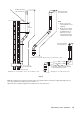
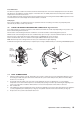
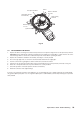
6.2 PREPARE FOR SERVICING - Fig. 28
1. Ensure the electrical supply is isolated and the gas supply is off.
2. Release the two screws securing the control panel and lower the panel.
3. Remove the four screws securing the front case. Lift the case up and forwards to remove.
4. Disconnect the gas supply pipe union from the manifold.
5. Remove the two screws securing the air supply pipe and remove the pipe.
6. Remove the two screws securing the fan assembly to the combustion chamber front.
7. Remove the two pressure tubes, noting their positions.
8. Disconnect the electrode lead from the ignition generator and the in-line connector to the flame sensing electrode.
9. Remove the four nuts and washers and four screws securing the combustion chamber front assembly and remove the
assembly.
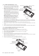
6.3 CLEANING THE BOILER
1. Remove any deposits from heat exchanger using a suitable soft brush. Do not use a brush with metallic bristles.
2. Check the condition of the combustion chamber insulation panels. Any damaged panels must be replaced. (Refer to
Component Replacement, Section 7.19).
3. Check the condition of the burner injector on the combustion chamber front assembly, carefully clean them with a soft
brush if necessary - Do not use a brush with metallic bristles as this might damage the injector.
4. Remove any deposits from the heat exchanger coils. This can be done by suction or water sprayed onto the coils.
Ensure all electrical components are protected from water. Any water used to clean the heat exchanger will drain to the
condensate trap.
5. Unscrew and replace the injector should it appear damaged.
6. Remove the four screws securing the burner (see Fig. 29) and remove the burner. Clean the burner with a soft brush
and check that the flame ports are clear. Blockages may be removed with a stiffer brush. Tap the burner, open end
down, to remove any deposits from inside.
7. Check the condition of the electrodes.
8. Check the spark gap, positioning and height of the electrodes, see Fig. 29.
9. Unscrew the condensate trap drain cap to remove any deposits.
Note: Before removing the cap, ensure that the water released from the trap can be contained to avoid spillage.
The trap will contain no more than 200 cc of condensate water. Replace the drain cap.
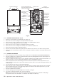
Fig. 28
Front case locating pins
Front case fixing screws
Combustion chamber
front assembly
Gas pipe union
Air supply pipe
fixing screw
Air supply pipe
fixing screw
Air supply pipe
Pressure tube
connections
Viewing window
Four nuts and washers and
four screws securing combustion
chamber front assembly
Flue gas
sampling point
Fan assembly
fixing screws
Fan assembly
Manual air vent
Expansion vessel
test/fill point
Ignition generator
Flame sensing
electrode