
Technical data
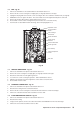


38
Alpha InTec C and X - Wiring Diagrams
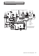
8.2 FUNCTIONAL FLOW WIRING DIAGRAM
Alpha Control
(Optional)
1
2
3
4
Pump
Gas Valve
Flow
Sensor
DHW Inlet
Sensor (optional)
System Pressure Switch
Fuse 3.15 AF
(on PCB)
230/240V ~ 50Hz
Fuse 3A
Remove link to connect
external control
N
L
N
DHW Sensor
External Sensor
(optional)
Flue
Sensor
Fan
Diverter
Valve Motor
Overheat
Thermostat
Heat Exchanger
Thermal Fuse
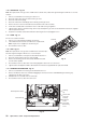
X16 X4
2
4
4
2
5
1
1
5
3
3
X12
4
2
3
6
5
17
X18
4
2
3
6
5
178
X14
4
2
3
6
5
1
7
8
9
10
11
X7
4
2
3
6
5
1
X17
3
5
4
1
2
6
X19
2 1
X3
L
N 3
4
X10
X9
X11
X15
1
1
2
2
3
3
Fuse
3.15 AF
Transformer
DHW SET
+
CH SET
+
B A
X5
12
3
4
5 6
X8
1
X6
R2
N
Spark
Generator
N
N
DHW Flow Switch
Climatic Control (low voltage)
(optional)
X3
L
X3
4
X16
1
X3
N
X16
3
X9
2
2
1
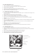
PCB
Note: Main Terminal Block
PCB Connection
To connect external controls remove link
from terminals 1 and 2 and connect 240 V
switched live to terminal 1.
(24 V DC)
(15 - 20 V DC)
+
-
X3
3
Flame Sensing
Electrode
BUS