An open vented central heating and mains pressure hot water supply appliance with a thermal store designed specifically for use with solar energy Design, Installation & Servicing Instructions Model Numbers BMA 215 OV-SOL BMA 225 OV-SOL BMA 235 OV-SOL BMA 245 OV-SOL BMA 265 OV-SOL BMA 285 OV-SOL All models comply with the water heater manufacturers specification for integrated thermal stores ISSUE 5: 06-08
CONTENTS ISSUE 5: 06-08 Section The code of practice for the installation, commissioning & servicing of central heating systems Page DESIGN Introduction Technical Data System Details 3 6 15 INSTALLATION Site Requirements Installation Commissioning 22 23 32 SERVICING Annual Service Changing Components Short Parts List Fault Finding 37 37 38 40 ADDENDIX Addendix A Addendix B Addendix C Addendix D 41 42 44 45 Terms & Conditions 46 Building Regulations and Benchmark Commissioning The Building Reg
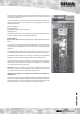
DESIGN These instructions should be read in conjunction with the Installation and Servicing Instructions issued by the manufacturers of the heat source e.g. the boiler used and the solar panel manufacturer. Any water distribution, central heating and solar installation must comply with the relevant recommendations of the current version of the Regulations and British Standards listed below:Gas Safety Regulations Building Regulations I.E.E.
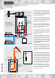
DESIGN F&E cisterns MCWS Safety/open vent Warning/ overflow pipe Expansion/cold feed BMA OV SOL 245 model S1/2 * NOT REQUIRED unless the heating system incorporates mechanical thermostatic control valves eg. TRVs to all radiators or 2 port zone valves to each heating circuit. S6 S5 Extent of the components included with the BMA OV SOL appliance S4 S3 DHWS outlet MCWS inlet Full bore automatic bypass valve* CH system (radiators or underfloor) Boiler Figure 1.
DESIGN The Building Regulations L1A: New dwellings/L1B: Existing dwellings and the requirements set out in the Domestic Heating Compliance Guide specify that “where the mains water hardness exceeds 200ppm provision should be made to treat the feed water to water heaters and the hot water circuit of combination boilers to reduce the rate of accumulation of lime scale”.
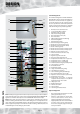
DESIGN Standard Equipment 25 36 35 27 29 28 26 32 20 30 19 31 18 17 21 35 15 16 22 24 7 10 14 5 8 23 6 12 4 9 33 3 13 38 11 2 1 37 TECHNICAL DATA 39 Figure 1.3 The standard configuration of the BoilerMate AClass OV SOL is shown opposite. The Appliance Controllers mounted inside the appliance, control the operation of the complete system. These are pre-wired to a terminal strip where all electrical connections terminate.
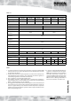
DESIGN Table 1.
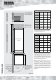
DESIGN Appliance Dimensions F&E cistern *350 300 BMA 215-225 OV SOL **350 **To comply with the access requirements of the Water Regulations. B *Minimum access / maintenance access above the appliance case.
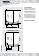
DESIGN Connection Details/Dimensions Connection Details/Dimensions - 215, 225 and 235 models Diagrams opposite show the connection details and dimensions for the BoilerMate A-Class OV SOL appliance. 545 - Cold Feed 530 - Domestic Hot Water 560 - Primary Flow 560 - Heating Return 520 - Primary Return 480 - Heating Flow 580 (620 including the door/clock) 560 The BoilerMate A-Class OV SOL units are supplied on an installation base to allow the pipe runs to connect to the appliance from any direction.
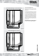
DESIGN Connection Details/Dimensions Connection Details/Dimensions - 265 model Diagrams opposite show the connection details and dimensions for the BoilerMate A-Class OV SOL appliance. Cold Feed Domestic Hot Water Primary Flow Heating Return Heating Flow Primary Return 675 (715 including the door/clock) 640 Note: All dimensions will be updated in the next issue of the manual. Figure 1.
DESIGN Front Panel Controls The front panel user controls are shown in the picture opposite and their functions are described below. Three different windows can be displayed in the visual display panel on the front of the appliance. Pressing the select button below the display allows you to move from one window to the next. Standard Display Window In normal automatic operation the display will be as shown opposite.
DESIGN The duty/location of the various sensors is as follows. Sensor Duty Location S1 T Overheat 1 S2 T Overheat 2 Top of store in dry pocket (S1 & S2 are in single housing) S3 T DHW in In cold water inlet pipe (Wet i.e. direct) S4 T DHW out In hot water outlet pipe (Wet i.e.
DESIGN Normal - standby state Indicate system status S2 Press S2 Sensor temperature reading S1 Press Press Press Press S1 S1 S1 S1 2 digit display S2 S1 Press S2 2 push buttons Main processor Control set-point reading Press Press Press Press S1 S1 S1 S1 Press Press Press Press S1 S1 S1 S1 Press Press Press Press S1 S1 S1 S1 Press Press Press Press S1 S1 S1 S1 Press S2 Fault code indicator lock outs Press S2 Appliance type 2 DIGIT ACB BOARD DISPLAY FLOW CHAR
DESIGN If the selected appliance code does not match with the ID resistor fitted to the appliance, then, an error ‘33’ will be displayed. A table showing this and other common fault codes is shown below. Fault Codes Fault code locations are numbered C0 - CF and c0 - cF. CO/cO locations hold the latest fault recorded. A code of FF indicates that the fault location is empty. If a sensor is faulty instead of a temperature it will show E1 if open circuit and E2 if short circuit.
DESIGN Hot and Cold Water System General A schematic layout of the hot and cold water services in a typical small dwelling is shown below. BoilerMate A-Class OV SOL will operate at mains pressures as low as 1 bar and as high as 5 bar although the recommended range is 2-3 bar. These pressures are the minimum dynamic pressures at the cold connection to the BoilerMate AClass at the time of the maximum calculated simultaneous demand.
DESIGN Hot and Cold Water System If it is proposed to use a ‘whole body’ or similar shower with a number of high flow/pressure outlets please check suitability with the Gledhill Technical Department before installation. Pipe Sizing / Materials To achieve even distribution of the available supply of hot and cold water, it is important in any mains pressure system, that the piping in a dwelling should be sized in accordance with BS 6700.
DESIGN Heating System F&E cisterns MCWS Warning/ overflow pipe Head recommended by boiler manufacturer as a minimum Safety/ open vent 250mm as a minimum Expansion/ cold feed Primary flow 6 metres maximum BMA OV SOL 245 model Primary return Boiler Full bore automatic bypass valve NOT REQUIRED unless the heating system incorporates mechanical thermostatic control valves e.g. T.R.V’s to all radiators or 2 port zone valves. Figure 1.
DESIGN Heating System Allowance for domestic hot water Equipment/Pipe Sizing and Materials The primary pipework connecting the boiler and the thermal store should be sized to achieve a maximum of 8°C rise across the boiler or the maximum temperature rise specified by the boiler manufacturer, whichever is smaller, but in any instance it should not be less than 22mm copper tube.
DESIGN Boiler Sited Below BoilerMate A-Class Any temperature controlled boiler can be used when the flow pipe from the boiler to the BoilerMate A-Class rises continuously. The primary flow also acts as the open vent/safety for the boiler, therefore no valve shall be fitted in the primary flow or open vent. F&E cisterns BMA OV SOL Primary return Primary flow Boiler Figure 1.11 Boiler sited above the BoilerMate Any boiler used must be fitted with an overheat thermostat i.e.
DESIGN A schematic layout of a solar system incorporating a BoilerMate A-Class OV SOL appliance is shown above. Solar System SC - Collector flow temperature sensor 5 amp junction box Solar panel (collector) On this basis, the flow and return pipework from the solar panel(s) (collectors) should be run directly from the panel to the BoilerMate A-Class OV SOL.
DESIGN relief valve and the necessary length of pre-insulated corrugated stainless steel pipework and sensor cable to complete the solar installation can be supplied by Gledhill. Please ring our Technical Sales Department for details. If it is proposed to use copper pipework, the components and insulation will need to take account of the extremely high temperatures and pressures which can be experienced, and the ethylene glycol antifreezes which are used.
INSTALLATION Site Requirements The appliance is designed to be installed in an airing/cylinder cupboard and the relevant minimum dimensions are provided in the Technical Data section. Because of the ease of installation we recommend that the cupboard construction is completed and painted before installation of the appliance. The cupboard door can be fitted after installation. If the unit needs to be stored prior to installation it should be stored upright in a dry environment and on a level base/floor.
INSTALLATION Preparation/placing the appliance in position. Details of the recommended positions for termination of the first fix pipework are provided in section the Technical Data section. The pipework can be located or its position checked using the template provided with each appliance. If these have been followed installation is very simple and much quicker than any other system. The appliance is supplied shrink wrapped on a timber installation base.
INSTALLATION Connection/Supply Arrangements 2 4 The position of the pipework connections is shown opposite. Dimensions are shown in the Technical Data section. 1 5 All the connections are also labelled on the appliance. It is essential that the pipework is connected to the correct connection.
INSTALLATION Note: When fitting the cistern, it must not be more than 6 metres above the base of the BoilerMate A-Class OV SOL appliance. The open vent must have a continuous rise from the appliance to its discharge point above the F&E cistern. Check and comply with the requirements of the Water Regulations/boiler manufacturer regarding the arrangement of the open vent.
INSTALLATION 1 2 3 4 UPR 15/50 Modulating Solar Pump 147DI_2 147SC-0-1 BoilerMate OV Solar Mode> Normal Br G Y J5 J1 1 Status LED Flow signal V 2 V 3 4 Wh R Wh Wh R J6 J3 J2 Sensor Body Temperature signal Pin numbers PE Pipe system J7a J7b J9 TWO CHANNEL DIGITAL CLOCK HOT CH WATER CH1 CH2 L ~ 2 1 3 4 5 Normally Open Zone Valve A B Normally Closed Zone Valve 2 2.5 mm SID Silicone 2 2.5 mm SID Silicone 2 2.5 mm SID Silicone A 2 Br Br Br 2 3 2 4.0 mm Tri-Rated 2.
INSTALLATION 5 S1 & S2 S3 Y G 6 R Br Wh Br Wh Bl Bl R Bl Y Y B B B Br Wh Br S5 Y Y White Covering Wh O Wh O O Wh Br S6 Br O B Bl R R ID_RESISTOR Br S4 7 Br Br Wh WIRE COLOUR LEGEND S1 & S2 Store overheat sensors S3 Cold Water IN S4 Domestic Hot Water OUT S5 R Bl Red Blue Bottom store sensor Br B Brown Black S6 Middle store sensor Or Orange S7 1K5 Resistor ID_Resistor (White) Y Yellow Sc Sz Dedicated Solar Zone 20K Wh G/Y White Green / Yellow Sr Solar
INSTALLATION Clamp the cables in the clamps provided below the terminal connections and ensure all cables are routed to avoid hot surfaces. Electrical Connection The BoilerMate A-Class OV SOL is pre-wired to DIN rail terminals from the A.C.B. and plumbers are well able to complete the electrical installation provided they adhere strictly to the IEE Requirements for Electrical Installations BS 7671.
INSTALLATION The BoilerMate A-Class OV SOL incorporates a pump overrun for the boiler pump. If a permanent live is required for the boiler then use L3 which is live whenever the power ON/OFF rocker switch is in the ON position The boiler manufacturers wiring instructions should be read in conjunction with this manual. Before switching on the electrical supply check all the factory made terminal connections to ensure they have not become loose during transit.
INSTALLATION Electrical Power/Control Supplies WARNING: THE BOILERMATE A-CLASS OV SOL IS FITTED WITH AN ELECTRIC BACKUP SYSTEM ‘SWITCH’. IMPORTANT: ELECTRICIAN/INSTALLER PLEASE NOTE. THE 2 x 16A MCB’s (MCB1 and MCB2) FOR THE ‘SWITCH’ ELECTRIC BACKUP SYSTEM ARE SUPPLIED SET IN THE ‘OFF’ POSITION BY AN ADHESIVE WARNING LABEL. MCB3 IS SUPPLIED SET IN THE ‘ON’ POSITION.
INSTALLATION Connection to BoilerMate OV SOL elec terminals Connection to BoilerMate OV SOL heating flow pipe Connection to BoilerMate OV SOL heating return pipe Zoned Heating Systems If a zoned heating system (or a separate towel rail circuit) is required, this can be provided in the conventional way from the main heating flow and return.
INSTALLATION Domestic Water and Heating Systems Cleansing the Primary System Open the incoming stop valve and fill the domestic mains cold and hot water systems. Fill the whole of the primary heating system with potable water through the feed and expansion cisterns. When determining the quantity of cleanser required, be sure to allow for the increased volume of water in the primary circuit due to the thermal store - see the Technical data section for volumes.
INSTALLATION Once the system is finally filled turn down the servicing valve for the ballvalve in the F & E cistern to the point where the warning/overflow will cope with the discharge arising from a ballvalve failure. Cleansing Hot/Cold Water System Treatment Fully flush and if necessary chlorinate the hot and cold water system in accordance with the recommendations in the Model Water Byelaws and BS 6700.
INSTALLATION Commissioning the Space Heating • The central heating is best commissioned when the store is hot and therefore should be carried out after commissioning the BoilerMate A-Class OV SOL/Primary system. • Set channel 2 of the digital clock to continuous operation mode and ensure that the room thermostat is calling for heat. This will be indicated by display segments V1.3 and V1.4 being on respectively.
INSTALLATION Filling/Commissioning The Solar System Using A Solar Filling Tank/Pump NB: THE MINIMUM SYSTEM PRESSURE SHOULD BE SET AT NO LESS THAN 1.3 BAR THE EXPANSION VESSEL PRESET PRESSURE SHOULD BE SET AT NO LESS THAN 1.0 BAR. Page 35 Flush/drain connection Flow from pump Fill connection Figure 1.15 Quarter turn regulating/ isolating valve Figure 1.16 1 Note: You should only fill the collector when there is no direct irradiation from the sun (or cover the collectors).
INSTALLATION Important Do’s and Don’ts Hand over to User 1. DO check the incoming mains water pressure and flow rate are adequate. (The preferred range of mains pressure is 2-3bar). • Explain the system and the BoilerMate A-Class OV SOL appliance controls to the user. 2. DO check that all connections are in accordance with the labelling on the thermal store. 3.
SERVICING Annual Servicing No annual servicing of the BoilerMate A-Class OV SOL appliance is necessary. However, if required, the operation of the controls and a hot water performance test can be carried out when servicing the boiler to prove the appliance is working satisfactorily and within its specification. At the same time, a check should be made of the solar system pressure/expansion vessel charge pressure along with a visual check of the solar panels.
SERVICING Key No. Supplier/Components Stock Code No.
1 2 3 4/28 5 6/14/15 7/9 8/10 11 12 13 16 17 18 19 20 21 22 23 24 25 26 27 29 30 31 32 33 34/35 36 Page 39 SHORT PARTS LIST SERVICING
SERVICING Fault Finding 3. Causes of ‘Unsatisfactory Space Heating’ Despite everyones best efforts some problems could occur and lead to complaints from the householder. Check the boiler thermostat - this should be set at maximum. Check that the boiler flow temperature is adequate to satisfy the store sensor. Check the operation and the settings of the heating programmer and the room thermostat. Check that the heating system pump is circulating the water to the radiator circuit.
APPENDIX Water Savings Water Related Costs Can Be Reduced By Good Plumbing Practice 1 2 1 1 2 tap half open Unregulated Over 20 l/m Fitted with regulator 5, 6 or 8 l/m 2 2 TAPS & MIXERS 4 Fixing Options For Taps & Mixers 1. MK Range - Combined Regulators & Aerator for screwing onto Taps & Mixers with internal or external threads on their noses.Anti Vandal models also available.
APPENDIX Manifolds Two sets of manifolds are available as an optional extra. Each set comprises a separate hot and cold water manifold. Both are provided with a 22mm inlet connection located centrally. All outlet connections are 15mm compression. The centre to centre dimension of each branch is 55mm.
APPENDIX The pressure loss through a flow regulator at the designated flow rate is about 1.8 bar. Therefore for the flow regulator to control the flow rate at pre-set level, the inlet pressure must be greater than 1.8 bar. If the inlet pressure is lower, the flow rate will be correspondingly less than the pre-set values. The maximum equivalent pipe lengths from the manifold to the terminal fittings can be estimated from the above information and the resistance characteristics of the pipes.
APPENDIX C APPENDIX Page 44
APPENDIX MANUAL HANDLING OF APPLIANCE PRODUCTS Description Manual handling means any transporting or supporting of a load (including lifting, putting down, pushing, pulling, carrying or moving) by hand or bodily force. Scope This assessment will cover the largest Appliance, namely ElectraMate, GulfStream, BoilerMate, SysteMate, PulsaCoil, Accolade and Stainless Lite manufactured by Gledhill. The maximum weight of the largest product in each range is 98kg and the size is 595 x 595 x 2020 mm high.
Gledhill (Water Storage) Ltd TERMS AND CONDITIONS AMD. JUNE 2008 CONDITIONS OF SALE & GUARANTEE TERMS 1. Gledhill (Water Storage) Ltd (“We” or “Gledhills”) only do business upon the Conditions which appear below and no other. Unless we so agree in writing these Conditions shall apply in full to any supply of goods by us to the exclusion of any Conditions or terms sought to be imposed by any purchaser.
9.4. 9.4.1.
The code of practice for the installation, commissioning & servicing of central heating systems