
Technical data


Page 4
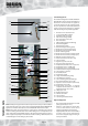
DESIGN
INTRODUCTION
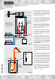
CH system
(radiators or underfloor)
Full bore
automatic
bypass valve*
DHWS outlet
Warning/
overflow
pipe
MCWS
Safety/open vent
Expansion/cold feed
Extent of the
components
included with
the BMA OV SOL
appliance
*
MCWS inlet
BMA OV SOL
245 model
S6
Figure 1.1
S5
S1/2
Boiler
S4
S3
NOT REQUIRED unless the
heating system incorporates
mechanical thermostatic
control valves eg. TRVs to all
radiators or 2 port zone valves
to each heating circuit.
F&E cisterns
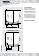
The arrangement of a typical BoilerMate A-Class
OV SOL installation is shown schematically
opposite in Figures 1.1 and 1.2. The basic unit
incorporates all the necessary controls to allow
the system to operate automatically once it has
been properly commissioned.
One cistern complete with ballvalve and
overflow connector is provided separately with
each 215-225 model BoilerMate A-Class OV SOL
appliance. This is normally fitted in the same
cupboard as the BoilerMate appliance.
Two cisterns complete with ballvalve and
overflow connector are provided separately
with the 235-285 model BoilerMate A-Class OV
SOL appliances, for remote fixing on site by the
installer as shown in Figure 1.1.
The principle of a BoilerMate A-Class OV SOL
is to separate the heat generator e.g. a boiler
from heat emitters (radiators) by a thermal store,
which evens out the fluctuating demands for
heating and hot water.
The BoilerMate A-Class OV SOL appliance
generally follows the principles of the standard
BoilerMate A-Class OV appliance but is fitted
with a separate set of coils to allow it to
maximise the available amount of heat available
from the solar panels/controls. This is then
used to supplement both the heating and
hot water systems.
Because this product does not require a safety
discharge from a temperature and pressure
relief valve, any installations will be easy to
incorporate into the building and will not suffer
from the problems associated with using PVCu
soil stacks to take the discharge from unvented
cylinders.
An important feature of these appliances is that
hot water can be supplied directly from the
mains at conventional flow rates without the
need for temperature and pressure relief safety
valves or expansion vessels. This is achieved
by passing the mains water through a plate
heat exchanger. The outlet temperature of the
domestic hot water is maintained by a printed
circuit board (A.C.B.), which controls the speed
of the pump circulating the primary water from
the store through the plate heat exchanger.
The solar pump/pipework can get extremely hot
and all solar pipework fitted to the appliance is
therefore provided with suitable insulation.
However, care should be taken, particularly in
high solar gain conditions.
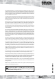
Extent of the
components
included with
the BMA OV SOL
appliance
Pressure
gauge
BMA
OV SOL
SZ
Figure 1.2
Expansion
vessel
PRV
Solar Panel
SC
Mounted horizontally
on top of the appliance
Temp. Gauge
Check Valve
Fill and
flush valves
0
20 100
120
40 80
60