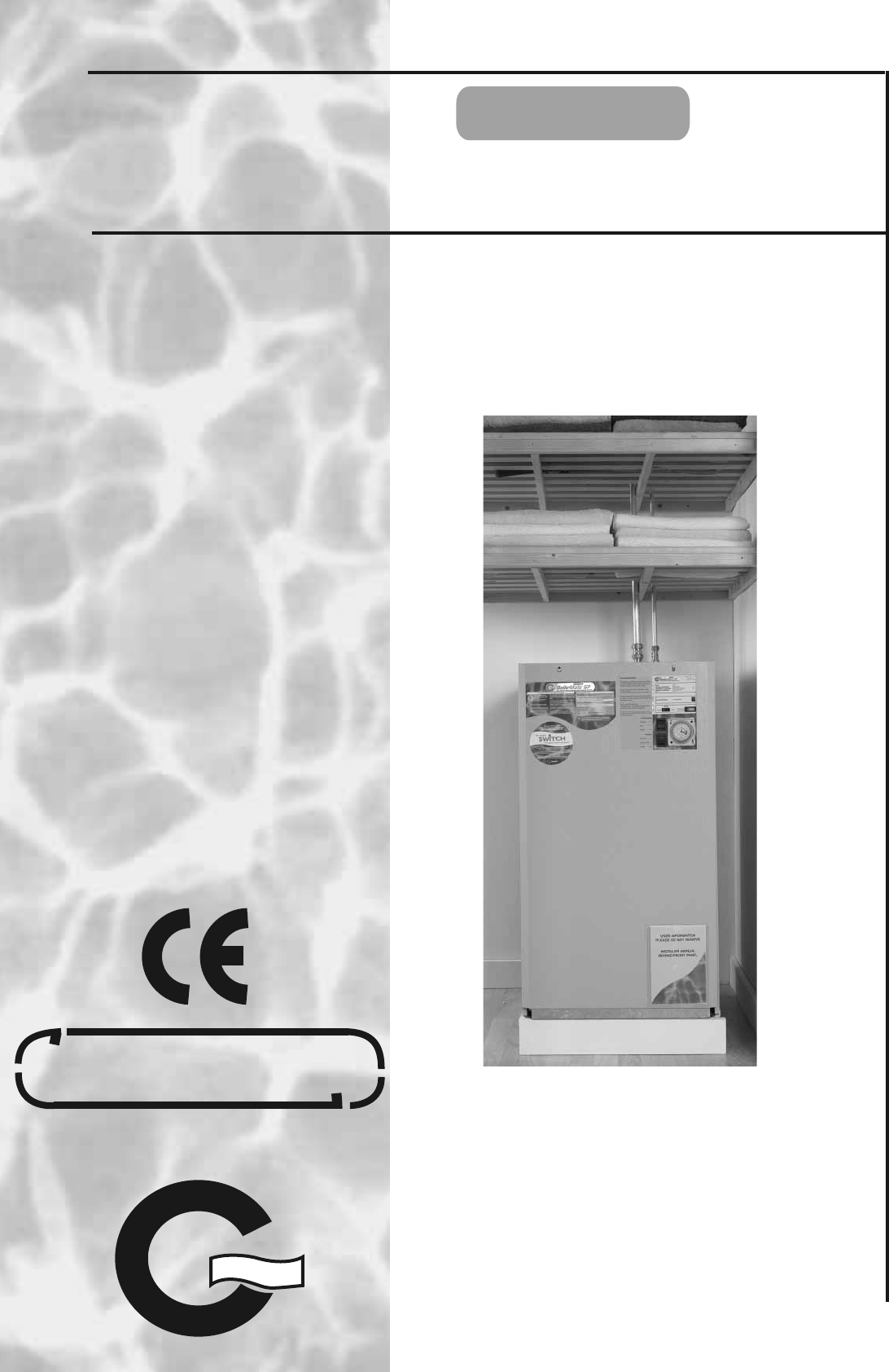
A-CLASS BoilerMate SP DESIGN, INSTALLATION AND SERVICING INSTRUCTIONS Gas Council Approved Reference Numbers 89-317-14 / BMA 120 SP 89-317-15 / BMA 140 SP 89-317-16 / BMA 180 SP 89-317-17 / BMA 200 SP 89-317-18 / BMA 220 SP benchmark TM A SEALED CENTRAL HEATING AND MAINS PRESSURE HOT WATER SUPPLY SYSTEM INCORPORATING A THERMAL STORE ALL MODELS COMPLY WITH THE WATER HEATER MANUFACTURERS SPECIFICATION FOR INTEGRATED THERMAL STORES ISSUE 6: 06-08 The code of practice for the installation, commissioning
CONTENTS ISSUE 6: 06-08 Section benchmark Page 1.0 DESIGN 1.1 Introduction 3 1.2 Technical Data 5 1.3 System Details 13 2.0 INSTALLATION 2.1 Site Requirements 20 2.2 Installation 21 2.3 Commissioning 31 3.0 SERVICING 3.1 Annual Servicing 35 3.2 Changing Components 35 3.3 Short Parts List 36 3.
1.0 DESIGN 1.1 INTRODUCTION Description These instructions should be read in conjunction with the Installation and Servicing Instructions issued by the manufacturers of the heat source e.g. the boiler used.
1.0 DESIGN 1.
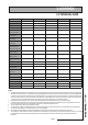
1.0 DESIGN 1.2 TECHNICAL DATA Model Weight (empty) BMA 120 SP BMA 140 SP BMA 180 SP BMA 200 SP BMA 220 SP 49.4 kg 51.8 kg 54.2 kg 56.5 kg 60.8 kg Weight (full) 174.4 kg 191.3 kg 201.2 kg 220.5 kg 245.
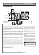
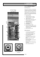
1.0 DESIGN 1.2 TECHNICAL DATA Standard Equipment The standard configuration of the BoilerMate A-Class SP is shown opposite. The Appliance Control Board (A.C.B.), mounted inside the appliance, controls the operation of the complete system. The A.C.B. is pre-wired to a terminal strip where all electrical connections terminate. It is supplied with the following factory fitted equipment:- 12 (F & E Tank not shown) 1. 2. 3. 4. 5. 10 4 3 5 2 7 6. 7. 8. 9. 10. 11. 12. 13.
1.0 DESIGN MM MM 1.
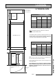
1.0 DESIGN 1.2 TECHNICAL DATA 115 50 COLD FEED OPEN VENT 530 15 150 210 DOMESTIC HOT WATER COLD FEED CYLINDER DRAIN PRIMARY RETURN TO BOILER CENTRAL HEATING RETURN TOWEL RAIL FLOW 560 CENTRAL HEATING FLOW PRIMARY FLOW 475 550 560 22 CL 65 65 Cut out area in base 115 190 220 230 All dimensions in mm - to centre line of pipework The BoilerMate A-Class units are supplied on an installation base to allow the pipe runs to connect to the appliance from any direction.
1.0 DESIGN 1.
1.0 DESIGN 1.
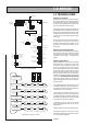
1.0 DESIGN 1.2 TECHNICAL DATA Sensor Tempature Readings Details of the various sensors S1-S6 used in the BoilerMate A-Class are shown opposite. The sensor reference i.e. S1 and the actual temperature at that sensor flash alternately on the display when selected. Sensors used in BoilerMate A-Class Sensor Connector J9 pins Location S1 T Overheat 1 6 & 14 S2 T Overheat 2 2 & 10 S3 T DHW in 3 & 11 In cold water inlet pipe (Wet i.e. direct) S4 T DHW out 4 & 12 In hot water outlet pipe (Wet i.e.
1.0 DESIGN 1.3 SYSTEM DETAILS Hot and Cold Water System General A schematic layout of the hot and cold water services in a typical small dwelling is shown below. BoilerMate A-Class will operate at mains pressures as low as 1 bar and as high as 5 bar although the recommended range is 2-3 bar. These pressures are the minimum dynamic pressures at the cold connection to the BoilerMate A-Class at the time of the maximum calculated simultaneous demand.
1.0 DESIGN 1.3 SYSTEM DETAILS Hot and Cold Water System Pipe Sizing / Materials To achieve even distribution of the available supply of hot and cold water, it is important in any mains pressure system, that the piping in a dwelling should be sized in accordance with BS 6700. This is particularly important in a large property with more than one bathroom.
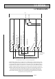
1.0 DESIGN 1.3 SYSTEM DETAILS Remote F&E Cistern 3 port divertor valve Cold feed Open Vent Automatic bypass valve Hot Out BM A-Class SP Mains Cold In Heating Circuit Summer use towel rail blanked connection Components fitted within appliance case Expansion Vessel Pressure Gauge/Filling Loop Boiler Pressure Gauge Relief/Safety Valve Optional sealed system kit Heating System General A schematic layout of the heating system in a typical small dwelling is shown above.
1.0 DESIGN 1.3 SYSTEM DETAILS Heating System All the recommendations with regard to pipework systems in this manual are generally based on the use of BS/EN Standard copper pipework and fittings. Pipe Sizing/Materials The BoilerMate A-Class SP is designed to be installed with any condensing or non condensing boiler which is suitable for a sealed heating system (i.e. fitted with an overheat thermostat) and is capable of delivering hot water at a minimum of 80oC.
1.0 DESIGN 1.3 SYSTEM DETAILS AAV Expansion Vessel AAV Heating System Pressure gauge Filling loop Pressure relief (safety) valve Boiler Remote F & E cistern Boiler Flow Boiler sited above the BoilerMate or with dipped flow and return pipes An automatic air vent will be required on the flow adjacent to the boiler and depending upon the pipe layout an automatic or manual air vent will also be required on the return adjacent to the boiler.
1.0 DESIGN 1.3 SYSTEM DETAILS Heating System Method of connecting two BoilerMates to one heat source If the primary flow and return pipework continuously rises from the boiler to the BoilerMate the recommended method for connecting two BoilerMates to one heat source is to fit the BoilerMates as normal but to provide a single check valve on the common primary return (to boiler) - see diagram below. The heating and hot water from each appliance must serve separate zones/bathrooms within the property.
1.0 DESIGN 1.3 SYSTEM DETAILS Heating System Expansion Vessel Requirements The BoilerMate expansion vessel is pre-charged to 1.0 bar. The maximum water content of the heating system (boiler + radiators + connecting pipework + primary coil but NOT store volume) must not be greater than those shown in the table below. A figure of 4.5 litres/kW of installed radiator capacity can be used for a preliminary assessment of the water content of the heating system.
1.0 DESIGN 1.3 SYSTEM DETAILS "OILER-ATE! #,!33 ‘Switch’ /&& 3,/7 &,!3().' -%$)5- &,!3().' 2!0)$ &,!3().' /. .ORMAL @3WITCH FAILURE @3WITCH BACKUP SELECTED /VERHEAT SAFETY TRIP @3WITCH /N 053( "544/. 4O RESET APPLIANCE -/$% @3WITCH This must NOT be used to provide hot water only in summer if the main system is working correctly. #ONTROL CIRCUIT POWER SUPPLY Full details of the electrical requirements are provided in Section 2.1 Site Requirements and 2.2 Installation.
2.0 INSTALLATION 2.1 SITE REQUIREMENTS The appliance is designed to be installed in an airing/cylinder cupboard and the relevant minimum dimensions are provided in section 1.2 Technical Data. Because of the ease of installation we recommend that the cupboard construction is completed and painted before installation of the appliance. The cupboard door can be fitted after installation.
2.0INSTALLATION 2.2 INSTALLATION Preparation/placing the appliance in position. Details of the recommended positions for termination of the first fix pipework are provided in section 1.2 Technical Data. The pipework can be located or its position checked using the template provided with each appliance. If these have been followed installation is very simple and much quicker than any other system. The appliance is supplied shrink wrapped on a timber installation base.
2.0INSTALLATION 2.
2.0INSTALLATION 2.
2.0 INSTALLATION 2.2 INSTALLATION Pipework connections The position of the pipework connections is shown opposite. The connection sizes and dimensions are listed in Section 1.2 Technical Data. All the connections are also labelled on the appliance. It is essential that the pipework is connected to the correct connection. ! Connections A, B, D, E and F are plain ended copper pipe. Connections C, G and H are compression fittings. Connection I is RC½ (½ in BSPT internal).
2.0 INSTALLATION 2.2 INSTALLATION It is normally envisaged that the feed and expansion cistern will be located in the same cupboard as the BoilerMate appliance itself to maintain a dry roof space.
2.0 INSTALLATION 2.2 INSTALLATION Electrical Connection - Standard Appliance The BoilerMate A-Class SP is pre-wired to DIN rail terminals from the A.C.B. and plumbers are well able to complete the electrical installation provided they adhere strictly to the IEE Requirements for Electrical Installations BS 7671. All the terminals are suitably labelled. G/Y G/Y BR BR 16A Note: Do not attempt the electrical work unless you are competent to carry it out to the above standards.
2.0 INSTALLATION 2.2 INSTALLATION The BoilerMate A-Class incorporates a pump overrun for the boiler pump and terminal L1 on the terminal strip (as shown on page 23) should only be used if the boiler requires a permanent live for another purpose. The boiler manufacturers wiring instructions should be read in conjunction with this manual. Before switching on the electrical supply check all the factory made terminal connections to ensure they have not become loose during transit.
2.0 INSTALLATION 2.2 INSTALLATION Electrical Power Supplies - BoilerMate A-Class with Switch. WARNING: THE BOILERMATE A-CLASS IS FITTED WITH AN ELECTRIC BACKUP SYSTEM ‘SWITCH’. IMPORTANT: ELECTRICIAN/INSTALLER PLEASE NOTE. THE 2 x 16A MCB’s (MCB1 and MCB2) FOR THE ‘SWITCH’ ELECTRIC BACKUP SYSTEM ARE SUPPLIED SET IN THE ‘OFF’ POSITION BY AN ADHESIVE WARNING LABEL. MCB3 IS SUPPLIED SET IN THE ‘ON’ POSITION.
2.0 INSTALLATION 2.2 INSTALLATION #ONNECTION TO "OILER-ATE 30 ELEC TERMINALS #ONNECTION TO "OILER-ATE 30 HEATING FLOW PIPE #ONNECTION TO "OILER-ATE 30 HEATING RETURN PIPE Zoned heating systems BoilerMate is available in a no clock/multi-zone version for use where a property has to have its space heating zoned. Where this appliance version is to be used it is recommended that the BoilerMate is located on a raised platform in the cupboard creating a space below the appliance to locate the zoning equipment.
N/C Br Or A Br AB Bl B Remove Link To Fit Room Thermostat 21-09-05 DATE Gr APPROVED DATE : SEPTEMBER 2005 G Bott DRN. GREEN G Or Wh E E E S. McGachie CH'KD. Br SIGN.
2.0 INSTALLATION 2.3 COMMISSIONING Open the incoming stop valve and fill the domestic mains cold and hot water systems. POWERFLUSHING/CLEANING OF THE HEATING SYSTEM Check and adjust as necessary the expansion vessel air pressure to the figure specified (normally 1.0 bar). If it is proposed to ‘powerflush’ the heating system we would recommend that the BoilerMate appliance is isolated from the heating system being cleaned. Failure to do this could seriously damage the appliance.
2.0 INSTALLATION 2.3 COMMISSIONING Once the system is finally filled turn down the servicing valve for the ballvalve in the F & E cistern, if fitted, to the point where the warning/overflow will cope with the discharge arising from a ballvalve failure. performance of the installed boiler. However the operation of the control system should be checked as follows: If an overflow is not fitted check and ensure that any temporary filling connections are removed/comply with the Water Regulations.
2.3 COMMISSIONING Commissioning Space Heating (b) Move the central heating control rocker to the constant position, set heating programmer to continuous and ensure that the room thermostat is calling for heat. This will be indicated by display segments V1.3 and V1.4 being on respectively. The BoilerMate controller will now:- This product is covered by the ‘Benchmark’ scheme and a separate commissioning/ service log book is included with this product.
2.0 INSTALLATION 2.3 COMMISSIONING Important Do’s and Don’ts DO check the incoming mains water pressure and flow rate are adequate. (The preferred range of mains pressure is 2-3bar). DO check that all plumbing and electrical connections are in accordance with the labelling on the thermal store. DO check and ensure the air pressure side of the expansion vessel is set at 1.0 bar (or as specified) DO ensure the BoilerMate A-Class SP is fitted on a sealed primary (i.e.
3.0 SERVICING 3.1 ANNUAL SERVICING No annual servicing of the BoilerMate A-Class is necessary. However, if required, the operation of the controls and a hot water performance test can be carried out when servicing the boiler to prove the appliance is working satisfactorily and within its specification. 3.2 CHANGING COMPONENTS Free of charge replacements for any faulty components are available from Gledhill during the in-warranty period (normally 12 months).
3.0 SERVICING 3.3 SHORTS PART LIST Key No.
3.0 SERVICING 3.4 FAULT FINDING Despite everyones best efforts some problems could occur and lead to complaints from the householder. Complaints can be grouped into the following three main categories:1. The system is noisy 2. Hot water service is unsatisfactory 3. Space heating is unsatisfactory The following checks should be carried out by the installer before calling the manufacturer. 1.
APPENDIX A WATER SAVINGS WATER RELATED COSTS CAN BE REDUCED BY GOOD PLUMBING PRACTICE. TAPS & MIXERS 1 1 2 1 2 TAP HALF OPEN Unregulated OVER 20 L/M 5, 6 OR 8 L/M Fitted with regulator 2 2 SHOWERS 4 FIXING OPTIONS FOR TAPS & MIXERS Unregulated 25 - 30 l/m Regulated 10 - 12 l/m Vast quantities of water are needlessly run off to waste due to Taps, Mixers and Showers discharging flow rates far in excess of the rates required for them to perform their duties.
APPENDIX B MANIFOLDS Manifold type: 1 - Stock Code MIP 050 (one bathroom, one en suite shower room, one cloakroom, one kitchen) Flow regulator (litres/minutes) Terminal fitting Hot water manifold outlets Quantity Cold water manifold outlets Quantity 18 Bath tap 1 1 9 Hand basin 3 3 12 Kitchen sink 1 1 9 Toilet cistern None 3 9 Shower 1 1 12 Washing machine 1 1 9 Dishwasher None 1 Total 7 11 Two sets of manifolds are available as an optional extra.
APPENDIX B The pressure loss through a flow regulator at the designated flow rate is about 1.8 bar. Therefore for the flow regulator to control the flow rate at pre-set level, the inlet pressure must be greater than 1.8 bar. If the inlet pressure is lower, the flow rate will be correspondingly less than the pre-set values. The maximum equivalent pipe lengths from the manifold to the terminal fittings can be estimated from the above information and the resistance characteristics of the pipes.
APPENDIX B The size of the distribution pipes supplying the manifold should be calculated using the method set out in BS 6700. A typical diagrammatic arrangement of a system using Manifold Type 1 is shown below. This is only meant to show the principles involved and the actual connection of fittings to the manifold will need to suit the arrangements shown on page 35.
APPENDIX C G U I D A N C E 2 N O T E S Inhibitor (Corrosion & scale protection of primary heating circuit) On filling the heating system and before the boiler is fired up, it is important to ensure the system water is treated with a suitable corrosion inhibitor, in accordance with the boiler manufacturer’s instructions.
APPENDIX D MANUAL HANDLING OF APPLIANCE PRODUCTS Description Manual handling means any transporting or supporting of a load (including lifting, putting down, pushing, pulling, carrying or moving) by hand or bodily force. Scope This assessment will cover the largest Appliance, namely ElectraMate, GulfStream, BoilerMate, SysteMate, PulsaCoil, Accolade and Stainless Lite manufactured by Gledhill. The maximum weight of the largest product in each range is 98kg and the size is 595 x 595 x 2020 mm high.
Page 44
Page 45 BOILERMATE A-CLASS SP