A sealed system central heating and mains pressure hot water supply appliance with thermal store designed specifically for use with solar energy Design, Installation & Servicing Instructions Addendum These instructions must be read in conjunction with the standard Boilermate A-Class SP Design, installation and servicing instructions before installation Model Numbers BMA 200 SP-SOL BMA 220 SP-SOL BMA 240 SP-SOL BMA 260 SP-SOL BMA 280 SP-SOL BMA 300 SP-SOL All models comply with the water heater manufacture
ISSUE 5: 06-08 Section Page DESIGN Introduction Technical Data 3 5 INSTALLATION Wiring Details Typical Pipework Arrangement Controls Filling/Commissioning Short Parts List 10 12 13 16 17 Terms & Conditions 22 The code of practice for the installation, commissioning & servicing of central heating systems Building Regulations and Benchmark Commissioning The Building Regulations (England & Wales) require that the installation of a heating appliance be notified to the relevant Local Authority Building
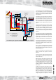
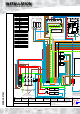
DESIGN T1 F&E cisterns Components fitted within the appliance case PRV Discharge pipe Commissioning/ filling assembly Solar Controls The arrangement of a typical BoilerMate A-Class SP Solar installation is shown schematically below. The basic unit which is covered by these instructions incorporates the Danfoss SH - E01 solar controller.
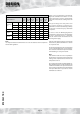
DESIGN Model Selection Data Table/Weights BMA 200 SP SOL BMA 220 SP SOL BMA 240 SP SOL BMA 260 SP SOL BMA 280 SP SOL BMA 300 SP SOL 2-3 2-4 3-5 3-5 4-5 5-6 1 2 2 2 2 3 2 1 2 3 3 3 (m2) 80 100 130 170 220 280 Empty (kg) 73 79 96 104 112 120 Full (kg) 233 260 313 366 411 472 Total (l) 160 181 217 262 299 352 Solar (l) 82 93 109 127 148 167 Model Reference Bedrooms Dwelling Bathrooms type En-Suite Max Floor Area Weight Volume Note: It is important
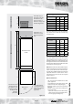
DESIGN F&E cistern *500 300 *250 BMA 200-220 SP SOL Appliance Dimensions B *If the F&E cistern is fitted with a ballvalve, this dimension will need to increase to 350mm to comply with the Water Regulations. *Minimum access / maintenance access above the appliance case.
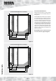
DESIGN Connection Details/Dimensions Connection Details/Dimensions - 200 model Diagrams opposite show the connection details and dimensions for the BoilerMate A-Class SP SOL appliance. 70 520 - Domestic Hot Water 545 - Incoming Cold Supply 560 - Combined Boiler/Heating Return 525 - Heating Flow 490 - Boiler Flow 620 (including the door/clock) 560 Note: All dimensions are shown in mm and are to the centre line of pipework/gland. 130 210 490 520 Figure 1.
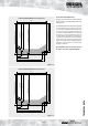
DESIGN Connection Details/Dimensions Connection Details/Dimensions - 240 model Diagrams opposite show the connection details and dimensions for the BoilerMate A-Class SP SOL appliance. 70 520 - Domestic Hot Water 545 - Incoming Cold Supply 560 - Combined Boiler/Heating Return 490 - Boiler Flow 525 - Heating Flow 620 (including the door/clock) 560 The BoilerMate A-Class SP SOL units are supplied on an installation base to allow the pipe runs to connect to the appliance from any direction.
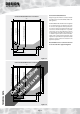
DESIGN Connection Details/Dimensions Connection Details/Dimensions - 280 model Diagrams opposite show the connection details and dimensions for the BoilerMate A-Class SP SOL appliance. 60 605 - Domestic Hot Water 610 - Incoming Cold Supply 650 - Combined Boiler/Heating Return 605 - Heating Flow 570 - Boiler Flow 700 (including the door/clock) 640 Note: All dimensions are shown in mm and are to the centre line of pipework/gland. 160 250 570 605 Figure 1.
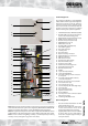
DESIGN Standard Equipment 14 13 27 21 The standard configuration of the BoilerMate A-Class SP SOL is shown opposite.The Appliance Controllers mounted inside the appliance, control the operation of the complete system. These are pre-wired to a terminal strip where all electrical connections terminate.
INSTALLATION 1 2 WIRE COLOUR LEGEND Br B Brown Black Or Orange Y Yellow Wh G/Y White Green / Yellow Gr Grey G Green TWO CHANNEL DIGITAL CLOCK CH HOT WATER ZONE 1 CH1 CH2 N L SCALE INHIBITOR T1 COM T2 AL P1 SOLAR CONTROLLER DANFOSS SH - E01 P-SL (PART No XB142) ON L ~ 1 3 2 5 4 1 Solar Pump High Store temperature interlock.
INSTALLATION 5 Duplex Sensor must be fitted in top saftey overheat pocket and secured R S1 & S2 S3 S5 & S6 Bl Bl R Bl Br Wh Br Y Y Wh Br B B B Wh Br O O Y G Br Wh Br O B Y Y Bl 8 R R FRONT PANEL Black Covering 2K2 A-ID A02 R B O Flat Ribbon Cable Or Br B R Or Br B Red LED B 'MODE' Switch B J31 J9 Bl A Push Button B B Br Br Duplex Sensor must fitted into S6 pocket i.e.
INSTALLATION SOLAR PANEL TYPICAL CONNECTION DIAGRAM TO BOILERMATE SP SOL Solar Panel Sensor Cable Junction Box Collector sensor T1 Internal Ceiling PRV No isolation valve should be installed between the solar circuit and the safety valve (pressure reducing valve). Expansion Vessel 60 40 80 20 100 120 0 1 bar Temperature Gauge and Check Valve FILL CONNECTION DRAIN CONNECTION OV / CF / Safety Expansion l /min 13 1 6 4 8 2 Flow Meter and Regulator 0.
INSTALLATION BoilerMate Heating/Hot Water Controls The current BoilerMate A-Class SP Sol incorporates separate heating/hot water and solar control systems. The BoilerMate A-Class SP Sol heating and hot water controls operate in the same way as the basic BoilerMate appliances but the single channel clock and the two rocker switches have been replaced by a two channel digital clock. (Channel 1 controls the gas boiler /hot water and Channel 2 the heating.
INSTALLATION Solar Controls The BoilerMate A-Class SP Sol appliance is supplied with a Danfoss electronic Solar Heat Regulator ref SH-EO1 built into the appliance and the necessary temperature sensors ref NTC 100k. Description of function The regulator controls the heat transmitted from the solar collector to the thermal store using the temperature differential between the sensors fitted adjacent to the solar collector and in the lower part of the thermal store.
INSTALLATION Function Test Annual Servicing The regulator is ready for operation when connected to the mains. The display becomes active and current temperatures are shown. Display updates once per minute. By pressing INFO button display updates immediately. No annual servicing of the BoilerMate A-Class SP SOL appliance is necessary. Regulator Fault Display If the temperature sensors have a fault, this is shown by the red LED being lit and F1 or F2 flashing. Call in the installer.
INSTALLATION FILLING/COMMISSIONING Filling/Commissioning The Solar System Using A Solar Filling Tank/Pump • Make sure all solar connections are fully tightened and all electrical connections are sound. • Make sure the BoilerMate A-Class SP SOL appliance has been commissioned and is working correctly. • Check the air side of the solar expansion vessel is set to the correct pressure (normally 1bar) and top up if necessary.
INSTALLATION Description Supplier/Components Stock Code No.
SHORT PARTS LIST INSTALLATION 1 2 3 4/24 5 6/12/13 7 8 9 10 11 14 15 16 17 18 19 20 21 22 23 26 27/28 29 30/31 34 Page 18
Page 19
Page 20
Page 21
Gledhill (Water Storage) Ltd TERMS AND CONDITIONS AMD. JUNE 2008 CONDITIONS OF SALE & GUARANTEE TERMS 1. Gledhill (Water Storage) Ltd (“We” or “Gledhills”) only do business upon the Conditions which appear below and no other. Unless we so agree in writing these Conditions shall apply in full to any supply of goods by us to the exclusion of any Conditions or terms sought to be imposed by any purchaser.
9.4. 9.4.1.
The code of practice for the installation, commissioning & servicing of central heating systems