
Technical data

Page 5
B
E
C
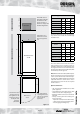
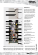
BoilerMate A-Class
SP SOL
300 *250A100 *500
D
F
Maintenance
access
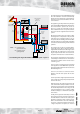
Figure 1.2
*Minimum access /
maintenance access
above the appliance
case.
*If the F&E cistern is
fitted with a ballvalve,
this dimension will
need to increase to
350mm to comply with
the Water Regulations.
The minimum clear
opening in front of
the appliance to be
at least the same as
the depth of the
appliance
plus 50mm.
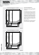
The cupboard door
opening will need to
take into account the
various sizes of
appliances.
F&E cistern
BMA 200-220 SP SOLBMA 240-300 SP SOL
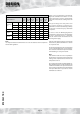
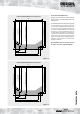
Appliance Dimensions
Model
Height
(A)
Width
(B)
Depth
(C)
BMA 200-SP SOL 1330 560 620
BMA 220-SP SOL 1330 560 620
BMA 240-SP SOL 1575 560 620
BMA 260-SP SOL 1575 610 670
BMA 280-SP SOL 1575 640 700
BMA 300-SP SOL 1485 710 770
The above dimensions are for the appliance
only and do not include the 100mm high
installation base.
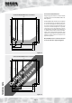
Minimum Cupboard Dimensions
Model
Height
(D)
Width
(E)
Depth
(F)
BMA 200-SP SOL 1980 660 630
BMA 220-SP SOL 1980 660 630
BMA 240-SP SOL 2175 660 630
BMA 260-SP SOL 2175 710 680
BMA 280-SP SOL 2175 740 710
BMA 300-SP SOL 2085 810 780
The above dimensions include the 100mm
high installation base and allow space for
installation/maintenance of the appliance only.
The height shown for the 200-220 models also
allows for the installation of the F&E cistern (with
no ballvalve) as shown opposite.
Note: With the 240-300 models, additional space
will be required for two feed and expansion
cisterns (each 280mm wide x 420mm deep x
300 high). This is NOT included in the minimum
cupboard dimensions shown above. Access
and maintenance space will also be required
for these cisterns.
Options at Extra Cost
• Hot and cold water manifolds for use with
plastic pipework.
• Scale inhibitor for mains water services with
hardness levels above 200ppm (mg/l).
• Ballvalve/overflow connector for automatic
fill model.
• Primary sealed system kit for fitting near
boiler comprising:
- Expansion vessel (size varies with model)
- 15mm 3 bar pressure relief (safety) valve
- Pressure gauge and filling loop
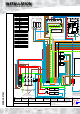
DESIGN
TECHNICAL DATA