
Technical data


Page 3
BOILERMATE
A-CLASS
SP SOL
1.0 DESIGN
1.1 INTRODUCTION
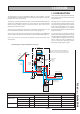
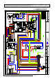
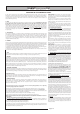
The arrangement of a typical BoilerMate A-Class SP Solar installation is shown
schematically below. The basic unit which is covered by these instructions incorporates
the Danfoss SH - E01 solar controller.
The appliance generally follows the principles of the standard BoilerMate A-Class SP
appliance but is fitted with a separate set of coils to allow it to accept the maximum
amount of heat available from the solar panels/controls. This is then used to
supplement the hot water system.
The operation of the appliance/solar system is controlled by a number of sensors. The
location and reference numbers of the various sensors is shown eg 2, S6.
Sensors S1/S2, S3, S4, S5 and S6 are connected to the appliance control PCB which
operates all the heating and hot water functions as the basic BoilerMate appliance.
Sensors T1, T2 and T3 are connected to the Danfoss controller and operate all the
solar functions.
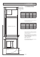
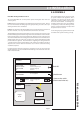
Model Selection Data Table/Weights
Model Reference BMA 200 SP SOL BMA 220 SP SOL BMA240 SP SOL
Dwelling type
Bedrooms 2-3 2-4 3-5
Bathrooms 1 2 2
En-Suite 2 1 2
Weight Empty (kg) - 79 -
Full (kg) - 260 -
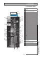
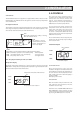
SensorT3 provides a high temperature interlock
to de-activate the solar pump at a temperature
of 90ºC in the store.
Although sensors T1 and T2 are wired in to the
solar controller the cable provided for Sensor
T1 (3 metres long) may require to be extended
by the installer dependant on the location
of the solar panels/appliance. (2 x 0.75mm
2
double insulated cable) up to a maximum total
length of 50 metres.
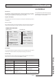
It is important that the installer checks the
hardness of the water supply and if this exceeds
200 ppm (mg/l) the factory fitted scale inhibitor
is ordered with the appliance at the time of
order to reduce the rate of accumulation of
scale in line with the requirements of the
Domestic Heating Compliance guide.
Solar
Controls
Solar
Collector
T1
V
V
Solar
Circuit
S4
S3
F & E Tank
(for thermal store)
S1/S2
T2
BoilerMate
A-Class SP Sol
T3
Heating/hot
water controls
(ACB)
Heating Return
Boiler
Mains
cold in
Hot out
Heating circuit
Sealed system kit
(available as an
optional extra)
Components fitted
within the
appliance
case
Note: The standard manual fill model BMA SP Sol
appliance is shown. A ballvalve and overflow are
available as an optional extra at the time of order
Schematic Diagram of Typical BoilerMate SP solar system
S6
S5
Automatic
Bypass
Heating Flow