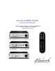
Benchmark DAC2 Series Instruction Manual Reference Stereo Preamplifier PCM and DSD D/A Converter Asynchronous USB
Safety Information Fuses CAUTION: FOR CONTINUED FIRE HAZARD PROTECTION ALWAYS REPLACE THE FUSES WITH THE CORRECT SIZE AND TYPE (0.5A 250 V SLO-BLO® 5 X 20 MM – LITTELFUSE® HXP218.500 OR EQUIVALENT). THE FUSE DRAWER INCLUDES TWO FUSES. ALWAYS REPLACE BOTH FUSES AT THE SAME TIME. Voltage Selection THE DAC2 IS EQUIPPED WITH A UNIVERSAL POWER SUPPLY. THERE IS NO VOLTAGE SELECTION SWITCH. AC VOLTAGE RANGE IS 88-264 VAC, 50-60 HZ.
Contents Benchmark Technologies Safety Information 3 Fuses Voltage Selection Power Cord Modifications Repairs 3 3 3 3 3 Contents 4 Features 5 Overview 6 Performance Improvements New Features Asynchronous USB 2.
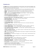
Features The DAC2 series is a reference-grade digital to analog converter, stereo system pre-amplifier, and headphone amplifier with infrared remote control. It supports D/A conversion of PCM sample rates up to 192 kHz, as well as direct DSD conversion.
Overview The DAC2 builds upon Benchmark’s highly successful DAC1 product family. Every DAC1 subsystem has been redesigned and upgraded to achieve higher performance. The DAC2 includes an updated version of Benchmark's highly-effective UltraLock™ jitter-attenuation system. y New features have been added to extend the versatility of the product, and improve the listening experience. These features include: native DSD conversion, asynchronous USB 2.0, asynchronous USB 1.
New Features Native DSD Conversion The DAC2 supports native DSD conversion. DSD signals can be delivered to the USB or Coaxial inputs in DoP 1.1 format. The DSD signal is then routed directly to a bank of 1bit DSD D/A converters. Four balanced 1-bit converters are summed together for each balanced output. Asynchronous USB 2.0 The USB interface supports DSD and 192 kHz, 24-bit PCM. The DAC2 generates the conversion clocks and totally eliminates the USB interface as a source of jitter.
Polarity Control Each digital input can be inverted to correct polarity problems. Some listeners report that polarity is incorrect on some recordings, and that they enjoy an improved listening experience when this is corrected. Bi-directional 12V Trigger (DAC2 HGC and DAC2 L model only) The 12V trigger can be connected to other audio components so that an entire audio system can turn on and off in a sequenced fashion. The DAC2trigger I/O could be connected to a preamplifier, power amplifier, or both.
stereo analog input (DAC2 HGC and DAC2 L model only), an additional analog output, 1 additional optical input, a digital pass-through, and high-efficiency low-noise power supplies. HPA2™ Headphone Amplifier (DAC2 HGC and DAC2 D model only) The HPA2™is one of the most transparent headphone amplifiers available. It also is able to deliver high current and/or high signal levels, and is well suited for a wide variety of headphones.
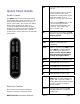
OFF Quick Start Guide Press the button once to put the unit in standby mode. Once engaged in standby mode, all the lights will remain on for 5 minutes, and the unit will turn off. Audio Inputs The DAC2 features two stereo RCA analog inputs (DAC2 HGC model and DAC2 L only) and five stereo digital inputs (2 coaxial, 2 optical, and 1 USB). The coaxial and optical inputs accept professional (AES) and consumer (S/PDIF) data formats at word lengths up to 24-bits.
The ‘Mute’ and ‘Dim’ functions are used to gracefully silence the DAC2. The ‘Mute’ function will fade the volume down before completely muting, and will ramp the volume up after un-muting. The ‘Dim’ function will also fade the volume down, but will not completely mute the audio. Dim is convenient for reducing volume to low levels during television or radio commercials or while conducting a conversation. The level of the ‘Dim’ volume setting can easily be set by the user with the remote control.
Front Panel DAC2 Series Instruction Manual Rev C Page 12
Input Status Display The DAC2 HGC and DAC2 L have sixteen LED status indicators on the front panel. The DAC2 D has fourteen LED status indicators on the front panel. Basic LED Explanation: DIM/MUTE – A solid red LED indicates that the unit is in DIM mode. A flashing red LED indicates that the unit is in MUTE mode. If the DIM/MUTE LED is not illuminated, then neither the DIM or MUTE function is engaged.
lit, this indicates that the signal coming into the DAC is DSD. Status Codes: • • • • • Single LED lit – ‘Normal’ operating condition with selected input Single flashing LED – error condition on selected input except A1 and A2 All LED’s lit – ‘Mute’ mode All LED’s lit except selected input – ‘Dim’ mode No LED’s lit – ‘OFF’ mode or no power Error Indication The Input Status Display will flash when an error occurs on the selected digital input.
Input Status Display Under normal operation, the Input Status Display shows which of the 7 inputs is selected. A single steady light indicates that a proper signal is present and ‘Normal’ volume mode is selected. When all LED’s are lit, the display indicates that the DAC2 is muted. When all but one LED are lit, the display indicates that the DAC2 is in ‘dim’mode. Flashing lights indicate error conditions.
HGC™ Volume Control Hybrid Gain Control™ "HGC" is Benchmark's unique Hybrid Gain Control™ system. The DAC2 combines active analog gain control, passive lowimpedance attenuators, a 32-bit digital gain control, and a servo-driven volume control. All inputs are controlled by the rotary volume control. This volume control moves in response to commands from the remote control. Analog inputs are never converted to digital, and digital inputs never pass through an analog potentiometer.
Rear Panel DAC2 HGC and DAC2 L DAC2 D Inputs only), 1 x USB, 2 x Optical, and 2x Coaxial. These inputs are selected using the frontpanel Input control, or the remote. The optical and coaxial can decode AES/EBU and S/PDIF input signals in either professional or consumer formats. TIP: The DAC2 will not decode AC3 or ADAT signals. The ‘Status Display’ will flash when AC3, ADAT, or other non-PCM input signals are connected to the selected digital input.
(including the USB input). The result is that all digital inputs have identical jitter performance. Analog Inputs – RCA Unbalanced ( DAC2 HGC and DAC2 L model only) The DAC2 HGC has 2 unbalanced stereo analog inputs via 2 pairs of RCA connectors. The analog inputs can be used for devices such as: • • • • • • Phono preamplifiers FM Tuners Tape Transports Analog VCR outputs iPod and MP3 devices Outputs from analog mixing consoles Computer Input – USB The USB input accepts a ‘B-type’ male USB 1.1 or USB 2.
276M standards specify 75-Ohm 1 Vpp professional format digital audio signals and these are commonly used in video production facilities. IEC 609588-3 specifies 75-Ohm 0.5 Vpp consumer-format digital audio signals (commonly known as S/PDIF). The coaxial inputs on the DAC2 are designed to accept either type of signal.
Outputs Analog Outputs Industry-standard XLR wiring: XLR pin 2 = + Audio Out XLR pin 3 = - Audio Out XLR pin 1 = Cable Shield CAUTION: If the balanced XLR outputs are wired to an unbalanced input (using a special adapter cable), pin 3 must be left floating. Shorting pin 3 to ground will increase the temperature of the output drivers, will increase power consumption, and may cause distortion. The DAC2 has one pair of balanced XLR outputs and two pairs of unbalanced RCA outputs.
Table 1). But, long un-balanced cables will generally suffer from hum problems due to ground loops. We highly recommend using balanced interconnects for long runs. HZ. THE PRODUCT MAY ALSO BE OPERATED FROM DC POWER OVER A VOLTAGE RANGE OF 125-373 VDC. Power Cord AC Power-Entry and Fuse Module The AC power input uses a standard IEC type connector. One USA-compatible power cord is included with DAC2 converters. IEC style power cords in country-specific configurations are available in your locality.
Internal Settings Removing Top Cover The DAC2 cover must be removed to gain access to the jumpers. Do not attempt to remove the faceplate or rear panel. CAUTION: The DAC2 contains static sensitive components and should only be opened by qualified technicians. Static discharge may cause component failures, may affect the long-term reliability, or may degrade the audio performance. Use a static control wrist strap when changing jumper settings.
Jumpers The following functions are jumper configured: • • • • Headphone Gain Range Adjustment (DAC2 HGC and DAC2 D model only) Headphone Switch Disable (DAC2 HGC and DAC2 D model only) XLR Output Pads Digital Pass Through Enable XLR Output Pad Selection (P8, P9, P10, and 11): Headphone Switch Disable (JP1 and JP2) (DAC2 HGC and DAC2 D model only): The DAC2 is configured so that the analog outputs will mute when a headphone plug is inserted into the left-hand jack.
Headphone Gain Reduction (JP3 and JP4) (DAC2 HGC and DAC2 D model only): The gain range of the HPA2™ can be set using jumpers JP3 and JP4. When jumpers are installed at position “A” the headphone amplifier gain is decreased by 20 dB. When jumpers are installed at position “B” the headphone amplifier gain is decreased by 10 dB. The ideal gain setting permits the user to set the front-panel Volume Control above 40% (10 o’clock) without the headphone volume being too loud.
Digital Pass Through The Digital Pass Through can be enabled by moving both P14 jumpers towards the faceplate shown in Figure 7. Once the jumpers are moved into the position shown in Figure 7, input D4 is active to function as a digital pass through. By default, D4 functions as a digital input so the jumpers are set according to Figure 8.
Rack Mounting An optional rack mount adapter allows the mounting of any two Benchmark System1™ products in a single rack space. A Blank Rack Panel can be added when only one unit is installed in the rack mount adapter. The System1™ Universal Rack Adapter and Blank Rack Panel are available from Benchmark. Call us, visit our website (http://www.BenchmarkMedia.com), or contact your dealer to purchase these accessories.
Benchmark Technologies Hybrid Gain Control™ "HGC" is Benchmark's unique Hybrid Gain Control™ system. The DAC2 combines active analog gain control, passive lowimpedance attenuators, a 32-bit digital gain control, and a servo-driven volume control. All inputs are controlled by the rotary volume control. This volume control moves in response to commands from the remote control. Analog inputs are never converted to digital, and digital inputs never pass through an analog potentiometer.
The USB subsystem remains active when the DAC2 is powered down. This prevents interruptions to the computer playback operations and eliminates the need to reconfigure the computer every time the converter is turned on. Jitter-Immune UltraLock2™ UltraLock2™ is an improved version of the UltraLock™ system used in the DAC1 product family. DSP processing is 32-bits, DSP headroom is 3.
least one dedicated low-noise voltage regulator. eliminated with a properly designed 0-Ohm headphone amplifier. HPA2™ Headphone Amplifier (DAC2 HGC and DAC2 D model only) The performance of the HPA2™ does not change when headphones are driven. THD+N measurements for no-load, 30-Ohm resistive loads, 30-Ohm headphone loads, and 600Ohm headphone loads are virtually identical. The HPA2™ will substantially improve the sound of 30 and 60-Ohm headphones.
Interface jitter accumulates as digital signals travel down a cable and from one digital device to the next. If we measure interface jitter in a typical system we will find that it is 10 to 10,000 times higher than the maximum allowable level for accurate 24-bit conversion. Fortunately, interface jitter has absolutely no effect on the audio unless it influences the conversion clock in an analog-to-digital converter (A/D) or in a digital-to-analog converter (D/A).
Jitter creates ‘new audio’ that is not harmonically related to the original audio signal. This ‘new audio’ is unexpected and unwanted. It can cause a loss of imaging, and can add a low and mid frequency ‘muddiness’ that was not in the original audio. Jitter induced sidebands can be measured using an FFT analyzer. Problem #2: Jitter can severely degrade the anti-alias filters in an oversampling converter. This is a little known but easily measurable effect.
audible jitter induced artifacts to an audio signal). What UltraLock™ converters cannot do: UltraLock2™ converters cannot undo damage that has already been done. If an A/D with a jitter problem was used to create a digital audio signal, then there is nothing that can be done to remove the damage. Jitterinduced sidebands are extremely complex and DAC2 Series Instruction Manual cannot be removed with any existing audio device.
Multi-Mode Asynchronous USB Audio System Plug it in and Start Listening… Immediately Benchmark's Advanced USB Audio technology is truly 'Plug and Play'. When connecting to a USB port on a computer running Windows or Mac OSX, the computer will automatically and instantaneously recognize the presence of the Benchmark USB device in USB 1.1, playing tracks up to 96 kHz 24-bit. Any audio played from the computer will then be routed to the Benchmark USB device immediately.
USB Driver Installation - Windows XP, Vista, 7 Note: The DAC2 driver is available for download at: http://www.benchmarkmedia.com/dac/dac2hgc/driver Before you install the driver, make sure the USB is unplugged before installation of the driver. 1. In the DAC2 Driver folder, double click “setup.exe.
2. A welcome screen will pop-up. Click “Next.
3. When you see the following screen, turn on the DAC2, and select USB as your input. By default, the DAC2 is shipped in USB 1.0 mode. You can enable your DAC2 in USB 2.0 mode in two ways. 1) Using your remote control, hold down the USB button on your remote control for 3-4 seconds until you see the 4X LED light up for 3-4 seconds. 2) From the front faceplate, hold down both input buttons until you see the 4X LED light up for 3-4 seconds. 4.
Press “Install” DAC2 Series Instruction Manual Rev C Page 37
5. When the installation begins you will see the following screen. Please be patient while the driver installs. Installation time is between 1-5 minutes. 6. Once the installation finishes a message at the top will say “Installation Complete.” Press “Next” to continue.
7. Click “Finish.” The Setup will close automatically and this completes the installation process. You can now enjoy music up to 192 kHz and DSD.
Performance Graphs Audio Precision FFT Idle Channel Noise, 0 dBr = 0 dBFS = 23 dBu +0 +0 -20 -20 -40 -40 -60 -60 d B r -80 -80 d B r A -100 -100 A -120 -120 -140 -140 -160 -160 0 2k 4k 6k 8k 10k 12k 14k 16k 18k 20k 22k 24k 26k 28k 30k 32k Hz Sweep Trace Color Line Style Thick Data Axis 1 1 1 2 Green Red Solid Solid 4 4 Fft.Ch.1 Ampl Fft.Ch.2 Ampl Left Right Comment DAC2 - FFT Idle Channel Noise.
Audio Precision FFT Idle Channel Noise - Low Frequency, 0 dBr = 0 dBFS = 23 dBu dx=120.470 Hz +0 dy=-1.126 dB +0 -20 -20 -40 -40 -60 -60 d B r -80 -80 d B r A -100 -100 A -120 -120 -140 -140 -156.413 -157.539 -160 -160 60.1566 75 50 25 100 125 150 180.626 175 200 225 250 275 300 325 350 375 400 Hz Sweep Trace Color Line Style Thick Data Axis 1 1 1 2 Green Red Solid Solid 4 4 Fft.Ch.1 Ampl Fft.Ch.2 Ampl Left Right Comment Cursor1 Cursor2 *-156.
Audio Precision DAC2 - FFT 10 kHz, 0 dBr = 0 dBFS = 23 dBu dx=10.0196 kHz +0 dy=-5.604 dB +0 -20 -20 -40 -40 -60 -60 d B r -80 -80 d B r A -100 -100 A -114.636 -120 -120.24 -120 -140 -140 -160 -160 0 2k 4k 6k 8k 10k 12k 14k 16k 18k 20.0391k 20k 22k 24k 26k 28k 30.0587k 30k 32k Hz Sweep Trace Color Line Style Thick Data Axis 1 1 1 2 Green Red Solid Solid 4 4 Fft.Ch.1 Ampl Fft.Ch.2 Ampl Left Right Comment Cursor1 Cursor2 *-114.636 dBr -116.
Audio Precision DAC2 - FFT 1 kHz, 0 dBr = 0 dBFS = 23 dBu dx=.995695 kHz +0 dy=-13.022 dB +0 -20 -20 -40 -40 -60 -60 d B r -80 -80 d B r A -100 -100 A -115.268 -120 -120 -128.29 -140 -140 -160 -160 0 200 400 600 800 1k 1.2k 1.4k 1.6k 1.8k 2.00391k 2k 2.2k 2.4k 2.6k 2.8k 2.99961k 3k 3.2k Hz Sweep Trace Color Line Style Thick Data Axis 1 1 1 2 Green Red Solid Solid 4 4 Fft.Ch.1 Ampl Fft.Ch.2 Ampl Left Right Comment Cursor1 Cursor2 *-115.268 dBr -115.
Audio Precision dx=40.4114 kHz +1 d B r DAC2 - FREQUENCY RESPONSE Fs = 96 kHz 10/24/12 16:02:03 dy=-0.011 dB +1 -0 -0 -0.009 -0.02 -1 -1 -2 -2 -3 -3 -4 -4 -5 -5 -6 -6 -7 -7 -8 -8 -9 -9 A d B r B -10 10.0021 5k 10k 15k 20k 25k 30k 35k 40.4214k 40k 45k -10 Hz Sweep Trace Color Line Style Thick Data Axis 1 1 1 2 Green Red Solid Solid 4 4 Anlr.Level A Anlr.Level B Left Right Comment Cursor1 Cursor2 -0.011 dBr A *-0.009 dBr -0.026 dBr A *-0.
Audio Precision DAC2 - Differential Phase Fs = 96 kHz dx=19.7956 kHz +1 dy=+0.23 deg +0.8 +0.6 +0.47 +0.4 +0.24 +0.2 d e g +0 -0.2 -0.4 -0.6 -0.8 -1 2.5k 5k 7.5k 10k 12.5k 15k 20.2555k 20k 22.5k 17.5k 25k 27.5k 30k 32.5k 35k 37.5k 40.0511k 40k 42.5k 45k Hz Sweep Trace Color Line Style Thick Data Axis 1 2 1 1 Green Red Solid Solid 4 4 Anlr.Phase Anlr.Phase Left Left Comment Cursor1 Cursor2 -0.09 deg *+0.24 deg -0.21 deg *+0.47 deg DAC2 - Differential Phase.
Audio Precision DAC2 - THD+N vs AMPLITUDE AT 1 KHZ (w/20 kHz LPF unweighted) Balanced Outputs, Relative to 0 dBFS, 0 dBFS = +23 dBu -96 -98 -100 -102 -104 d B r A -106 -108 -110 -112 -114 -116 -118 -120 -14 -13 -12 -11 -10 -9 -8 -7 -6 -5 -4 -3 -2 -1 -0 dBFS Sweep Trace Color Line Style Thick Data Axis 1 1 1 2 Green Red Solid Solid 4 4 Anlr.THD+N Ampl Anlr.THD+N Ampl Left Left Comment DAC2 - Balanced THD+N vs AMPLITUDE.at27 Graph Plot 7 - Balanced THD+N vs.
Audio Precision DAC2 - THD+N vs AMPLITUDE AT 1 KHZ (w/20 kHz LPF unweighted) Unbalanced Outputs, Relative to 0 dBFS, 0 dBFS = +7.2 dBu -95 -96 -97 -98 -99 -100 -101 -102 -103 -104 -105 d B r -106 A -109 -107 -108 -110 -111 -112 -113 -114 -115 -116 -117 -118 -119 -120 -14 -13 -12 -11 -10 -9 -8 -7 -6 -5 -4 -3 -2 -1 -0 dBFS Sweep Trace Color Line Style Thick Data Axis 1 1 1 2 Green Red Solid Solid 4 4 Anlr.THD+N Ampl Anlr.
Audio Precision DAC2 - THD+N vs AMPLITUDE AT 1 KHZ (w/20 kHz LPF unweighted) Headphone Outputs, Relative to 0 dBFS, 0 dBFS = +7.2 dBu -86 -88 -90 -92 d B r -94 -96 A -98 -100 -102 -104 -14 -13 -12 -11 -10 -9 -8 -7 -6 -5 -4 -3 -2 -1 -0 dBFS Sweep Trace Color Line Style Thick Data Axis 1 1 1 2 Green Red Solid Solid 4 4 Anlr.THD+N Ampl Anlr.THD+N Ampl Left Left Comment DAC2 - HEADPHONE - THD+N_VS_AMPLITUDE.
Audio Precision DAC2 - THD+N VS FREQ AT 0 dBFS (w/80 kHz LPF unweighted) Balanced Outputs -90 -92.5 -95 -97.5 d B -100 -102.5 -105 -107.5 -110 20 50 100 200 500 1k 2k 5k 10k 20k Hz DAC2 - THD+N vs FREQUENCY 80kHZ.at27 Graph Plot 10 - THD+N vs. FREQUENCY 80 kHz The analog output stages on the DAC2 have high slew rates and are capable of maintaining low THD levels at high frequencies even when driven to 0 dBFS.
Audio Precision dx=8.99682 kHz -90 d B DAC2 - THD VS FREQ AT 0 dBFS Balanced Outputs dy=+3.144 dB -90 -95 -95 -100 -100 -105 -105 -110 -110 -112.066 -115 -115.21 -115 -120 -120 -125 -125 -130 20 50 100 200 1.00318k 1k 500 2k 5k 10k 10k d B -130 Hz Sweep Trace Color Line Style Thick Data Axis 1 1 1 2 Green Red Solid Solid 4 4 Distortion.Ch.1 Harm Sum1 Ratio Distortion.Ch.1 Harm Sum2 Ratio Left Right Comment Cursor1 Cursor2 *-115.210 dB -115.165 dB *-112.
Audio Precision DAC2 - THD VS FREQ AT 0 dBFS - ALL OUTPUTS dx=8.99682 kHz -90 dy=+8.088 dB -90 -95 -95 -100 -100 -105 d B -105 -106.739 d -110 B -115 -114.827 -110 -115 -120 -120 -125 -125 -130 20 50 100 200 1.00318k 1k 500 2k 5k 10k 10k -130 Hz Sweep Trace Color Line Style Thick Data Axis 1 1 2 2 3 3 2 3 2 3 2 3 Blue Cyan Red Magenta Green Yellow Solid Solid Solid Solid Solid Solid 4 4 4 4 4 4 Distortion.Ch.1 Harm Distortion.Ch.2 Harm Distortion.Ch.1 Harm Distortion.
Benchmark Media Systems, Inc. DAC2 - THD+N vs Sample Rate, 1 kHz at 0 dBFS (w/20 kHz LPF unweighted) Balanced Outputs -90 -92.5 -95 -97.5 -100 -102.5 d B -105 -107.5 -110 -112.5 -115 -117.5 -120 40k 60k 80k 100k 120k 140k 160k 180k 200k Hz Sweep Trace Color Line Style Thick Data Axis 1 1 1 2 Green Red Solid Solid 4 4 Anlr.THD+N Ratio Anlr.THD+N Ratio Left Left Comment DAC2 - THD+N vs Sample Rate.
Audio Precision DAC2 - INTERFACE JITTER TOLERANCE - Distortion vs Jitter 3.456 kHz Test Tone at 0 dBFS, THD+N 22 to 22 kHz BW +0 20 -10 10 -20 5 -30 2 -40 d B 1 -50 500m -60 U I 200m -70 100m -80 50m -90 20m -100 -110 100 200 500 1k 2k 5k 10k 20k 50k 90k 10m Hz Sweep Trace Color Line Style Thick Data Axis 1 1 1 2 Green Red Solid Solid 4 4 Anlr.THD+N Ratio Dio.Interface Jitter Left Right Comment DAC2 THD+N (22-22kHz) (Green Trace) vs.
Audio Precision DAC2 - INTERFACE JITTER TOLERANCE FFT 10 kHz Test Tone at 0 dBFS, AES Jitter Tolerance Sweep +0 -20 -40 d B r -60 -80 A -100 -120 -140 0 2k 4k 6k 8k 10k 12k 14k 16k 18k 20k 22k 24k 26k 28k 30k 32k Hz Sweep Trace Color Line Style Thick Data Axis 1 2 3 4 5 6 7 8 9 10 11 12 13 14 15 16 17 18 19 20 21 22 23 24 25 26 27 28 29 30 31 2 2 2 2 2 2 2 2 2 2 2 2 2 2 2 2 2 2 2 2 2 2 2 2 2 2 2 2 2 2 2 Green Red Red Magenta Blue Cyan Green Yellow Red Magenta Blue Cyan Gr
Audio Precision +0 d B r A dx=9.00196 kHz DAC2 - 11K 12K IMD 11/06/12 08:15:12 dy=-6.731 dB +0 -10 -10 -20 -20 -30 -30 -40 -40 -50 -50 -60 -60 -70 -70 -80 -80 d B r A -90 -90 -100 -100 -110 -110 -120 -122.154 -130 -128.885 -120 -140 -140 -150 -150 -160 0 -130 1.01761k 2k 4k 6k 10.0196k 10k 8k 12k 14k 16k 18k 20k -160 Hz DAC2 - IMD 11K 12K.at27 Graph Plot 16 - IMD 11k 12K This plot demonstrates that the DAC2 has very low IMD distortion.
Specifications Audio Performance Fs = 44.1 to 96 kHz, 20 to 20 kHz BW, 1 kHz test tone, 0 dBFS = +24 dBu (unless noted) SNR – A-Weighted, 0 dBFS = +20 to +29 dBu 126 dB SNR – Unweighted, 0 dBFS = +20 to +29 dBu 123 dB THD+N, 1 kHz at 0 dBFS -109 dBFS, -109 dB, 0.00035% THD+N, 1 kHz at -1 dBFS -110 dBFS, -109 dB, 0.00035% THD+N, 1 kHz at –3 dBFS -113 dBFS, -109 dB, 0.00035% THD+N, 20 to 20 kHz test tone at –3 dBFS -112 dBFS, -108 dB, 0.00040% Frequency Response at Fs=96 kHz +0 dB, -0.04 dB (20 to 20 kHz) -0.
Audio Performance (continued) Maximum Lock Time after Fs change Soft Mute Ramp Up/Down Time Mute on Receive Error Mute on Lock Error Mute on Idle Channel 50/15 us De-Emphasis Enable De-Emphasis Method De-Emphasis Supported at 400 ms 50 ms Yes Yes No Automatic in Consumer Mode Digital IIR Fs = 32, 44.1, 48 kHz Group Delay (Latency) Delay – Digital Input to Analog Output (function of sample rate) 1.36 ms at 44.1 kHz 1.27 ms at 48 kHz 0.90 ms at 88.2 kHz 0.82 ms at 96 kHz 0.51 ms at 176.4 kHz 0.
Analog Audio Inputs Number of Analog Inputs (switch selected) Number of Channels Input Impedance 2 (RCA stereo pair - unbalanced) ( DAC2 HGC and DAC2 L model only) 2 20 k Ohms Maximum Input Level Maximum Input @ Factory-set Calibration Levels DC Blocking Capacitors on Analog Inputs Transient and Over-Voltage Protection on Analog Inputs Input Capacitance Analog-Input Gain Range +19 dBu +14 dBu Yes Series R and diode protection 10 pF Off to +0.5 dB (RCA in to RCA out) Off to +16.
Digital Audio Inputs Number of Digital Inputs (switch selected) Number of Channels Input Sample Frequency Range 5 (1 USB, 2 Optical, 2 Coaxial) 2 28 to 210 kHz (Coaxial) 28 to 96 kHz (Optical) Maximum Input Word Length Digital Input Impedance on Coaxial input (jumper selected) DC Blocking Capacitors on Digital Inputs Transient and Over-Voltage Protection on Digital Inputs Minimum Digital Input Level Jitter Tolerance (With no Measurable Change in Performance): 44.1, 48, 88.2, 96, 176.
Balanced Analog Outputs Number of Balanced Analog Outputs Output Connector Output Impedance 2 Gold-Pin Neutrik™ male XLR 60 Ohms (Attenuator off) 425 Ohms (Attenuator = 10 dB) Analog Output Clip Point Factory Set Home Theater Bypass Level (at 0 dBFS) Output Level Range (at 0 dBFS) In ‘Variable’ Mode 135 Ohms (Attenuator = 20 dB) +30 dBu +13 dBu (Attenuator = 10 dB) Off to +23 dBu (Attenuator off) Off to +13 dBu (Attenuator = 10 dB) Output Level Variation with Sample Rate (44.1 kHz vs.
HPA2TM Headphone Outputs (DAC2 HGC and DAC2 D model only) Number of Headphone Outputs Output Connectors Output Impedance Output Level Control Output Level Range (at 0 dBFS) into 60-Ohm Load Maximum Output Current Overload Protection (independent per channel) Bandwidth THD+N 2 ¼” TRS with switch on left-hand jack < 0.11 Ohms Stereo Control on Front Panel Off to +17 dBu 250 mA Current limited at 300 mA, Thermal > 500 kHz -106 dB, 0.0005% into 30 Ohms at +18 dBu (1.
AC Power Requirements Nominal Input Operating Voltage Range (VAC RMS) Frequency Power 100 – 240V 50-60 Hz < 0.5 Watts Idle 12 Watts Typical Program 15 Watts Maximum 5 x 20 mm (2 required) 0.5 A 250 V Slo-Blo® Type 90 – 260 47 – 63Hz Fuses Min/Max Operating range (VAC RMS) Dimensions Form Factor Depth behind front panel Overall depth including connectors but without power cord Width Height ½ Rack Wide, 1 RU High 8.5” (216 mm) 9.33” (237 mm) 9.5” (249 mm) 1.725” (44.
Regulatory Compliance FCC and RoHS Compliance Statements FCC Notice (U.S. Only) NOTICE: This equipment has been tested and found to comply with the limits for a Class B digital device, pursuant to Part 15 of the FCC Rules. These limits are designed to provide reasonable protection against harmful interference in a residential installation.
CE Certificates of Conformity DAC2 Series Instruction Manual Rev C Page 64
Warranty Information Benchmark 1 Year Warranty The Benchmark 1 Year Warranty Benchmark Media Systems, Inc. warrants its products to be free from defects in material and workmanship under normal use and service for a period of one (1) year from the date of delivery. This warranty extends only to the original purchaser. This warranty does not apply to fuses, lamps, batteries, or any products or parts that have been subjected to misuse, neglect, accident, modification, or abnormal operating conditions.
Benchmark Extended Warranty The Benchmark Extended 5* Year Warranty Benchmark Media Systems, Inc. optionally extends the standard one (1) year warranty to a period of five (5)* years from the date of delivery. *For the extended warranty to become effective, the original purchaser must register the product at the time of purchase either by way of the enclosed registration card or through the product registration section of the Benchmark Media Systems, Inc. website.
Copyright © 2007, 2008, 2009, 2012 Benchmark Media Systems, Inc. All rights reserved. Benchmark Media Systems, Inc. Benchmark Media Systems, Inc. 203 East Hampton Place, STE 2 Syracuse, NY 13206-1633 USA PHONE: +1-315-437-6300 FAX: +1-315-437-8119 www.benchmarkmedia.