Benchmark DAC1 HDR Instruction Manual Stereo Preamplifier w/ Remote Control, Digital-to-Analog Converter, Headphone Amplifier and Computer Audio Interface
Safety Information Voltage Selection CAUTION: THE FUSE DRAWER INCLUDES A VOLTAGE SELECTION SWITCH WITH TWO SETTINGS: ‘110’ AND ‘220’. CHECK TO SEE THAT IT IS PROPERLY CONFIGURED FOR YOUR LOCATION BEFORE CONNECTING AC POWER. Incorrect configuration may blow fuses or cause erratic operation. Repairs Modifications CAUTION: DO NOT SUBSTITUTE PARTS OR MAKE ANY MODIFICATIONS WITHOUT THE WRITTEN APPROVAL OF BENCHMARK MEDIA SYSTEMS, INC. MODIFICATION MAY CREATE SAFETY HAZARDS AND VOID THE WARRANTY.
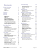
Internal Settings Contents Safety Information 2 Voltage Selection Repairs Fuses Modifications 2 2 2 2 Contents 3 Features 4 Overview 5 DAC1 Heritage Applications HDR-VC™ AdvancedUSB Audio™ Jitter-Immune UltraLock™ HPA2™ Headphone Amplifier High-Current Output Drivers ‘Audio-Always’ Design Philosophy Low-Noise Internal Power Supply Phase-Accurate Multi-Track and 5.
Features Reference-grade stereo system pre-amplifier with infrared remote control HDR-VC™ (High Dynamic Range Volume Control) - custom Alps motorized potentiometer Built-in DAC1 digital-to-analog audio conversion system - 2-channel, 24 bit/192 kHz Built-in HPA2™ reference-grade headphone amplifier - “0-Ohm”, high-current Built-in AdvancedUSB™ Computer Audio Interface – native 24 bit/96 kHz Remote control features: on/off, input select, volume, dim, and mute Dim and soft-mute level
Overview The DAC1 HDR is a reference-quality, 2channel stereo preamplifier with infrared remote control. It features Benchmark’s: • • • • • HDR-VC™ high dynamic-range volume control DAC1 192-kHz, 24-bit digital-toanalog audio converter AdvancedUSB Audio™ computer audio interface HPA2™ headphone amplifier UltraLock™ clock system DAC1 Heritage The pristine audio performance of the awardwinning DAC1 has made it the ‘Benchmark’ of stand-alone D/A converters.
AdvancedUSB Audio™ High-Current Output Drivers The USB input is compatible with Windows Vista/XP/2000 and Mac OS X with no driver installation or system configuration required (see www.benchmarkmedia.com/wiki for upto-date compatibility information). The DAC1 HDR features new high-current output drivers that are capable of driving 300-Ohm loads without an increase in distortion. They are also well suited for driving long cables or high-capacitance loads.
Low-Noise Internal Power Supply The internal power supply supports all international voltages with generous margins for over and under voltage conditions. It has excellent immunity to noise on the AC line and no external AC filtering is required. Phase-Accurate Multi-Track and 5.1 The DAC1 HDR is phase-accurate between channels at all sample rates, and is phase accurate between any combination of DAC1, DAC1 USB, DAC1 PRE, and DAC1 HDR converters at sample rates up to 96 kHz.
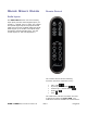
Quick Start Guide Remote Control Audio Inputs The DAC1 HDR features one stereo analog input (RCA) and five stereo digital inputs (3 x coaxial, 1 x optical, and 1 x USB). The coaxial and optical digital inputs accept professional (AES) and consumer (S/PDIF) data formats at word lengths up to 24-bits. The optical input is limited to 96 kHz sample rates. Use the coaxial inputs for 192 kHz applications.
before completely muting, and will ramp the volume up after un-muting. The ‘Dim’ function will also fade the volume down, but will not completely mute the audio. This is convenient to reduce the volume to low levels during television or radio commercials or to conduct a conversation. The level of the ‘Dim’ volume setting can easily be set by the user with the remote control.
Input Status Display Mute on Headphone Insertion Under normal operation, the Input Status Display shows which of the 6 inputs is currently selected. A single steady light indicates that a proper signal is present and ‘Normal’ volume mode is selected. When all LED’s are lit, the display indicates that the DAC1 HDR is muted. When all but one LED are lit, the display indicates that the DAC1 HDR is in ‘dim’-mode. Flashing lights indicate error conditions.
Front Panel Input Status Display Error Indication The DAC1 HDR has a six-LED status indicator on the front panel. The Input Status Display will flash when an error occurs on the selected digital input. The type of error is indicated by the frequency of the flashes.
Source Selector and ON/OFF Switch The rotary Source Selector control is located directly to the right of the Input Status Display. Rotate the knob to select an input. The rotary Source Selector switch is equipped with an on/off switch. Press the control knob to turn the DAC1 HDR on or off. The ‘ON/OFF’ function features a soft mute and soft un-mute function that responds very quickly. Because of this fast response, the ‘ON/OFF’ function also serves as a mute function.
HDR-VC™ Volume Control The front-panel HDR-VC™ volume control is a high-dynamic-range gain circuit built around a custom-made Alps potentiometer. The custom Alps pot is equipped with remotecontrollable motor drive. This potentiometer is equipped with a clutch which prevents damage from overriding the motor drive. If the pot is driven beyond the end of its range, it will not damage the motor. Also, if the pot is manually overridden, it will not damage the motor.
Rear Panel Inputs The analog inputs can be used for devices such as: • • • • • • Phono preamplifiers FM Tuners Tape Transports Analog VCR outputs iPod and MP3 devices Outputs from analog mixing consoles Computer Input – USB There are six stereo inputs on the DAC1 HDR: 1 x Analog, 1 x USB, 1 x Optical, and 3 x Coaxial. These inputs are selected using the front-panel Source Selector control. The optical and coaxial can decode AES/EBU and S/PDIF input signals in either professional or consumer formats.
The DAC1 USB is designed, tested and proven compatible with Windows Vista/XP/2000 and Mac OS X with no driver installation or system configuration required. For the up-to-date information about more recent operating systems and suggestions for optimization, go to: www.benchmarkmedia.com/wiki. TIP – Visit our computer audio application pages for the latest information on media players, media servers, operating systems, and audiorelated computer accessories: www.benchmarkmedia.
Output Level Switch The Output Level Switch is a three-position toggle switch located on the rear panel. The DAC1 HDR ships with this switch set in the Variable position. CAUTION: Do not set the ‘Output Level’ switch to ‘Calibrated’ if the DAC1 HDR is directly connected to a power amplifier or powered speakers. The ‘Calibrated’ will produce a high-level output that may be too loud for your speakers. Calibrated (UP) – Analog output levels are controlled by 10-turn internal trim controls.
Unbalanced RCA Analog Outputs AC Power-Entry and Fuse Module The Left and Right unbalanced outputs use standard RCA style jacks. The ground connections are bonded to chassis ground at the location where analog ground is bonded to the chassis. This minimizes the effects of ground loops caused by AC currents in the cable shield. The RCA output levels may be controlled from the front panel, or may be set to fixed levels using the internal Calibration Trimmers.
Internal Settings Removing Top Cover The DAC1 HDR cover must be removed to gain access to the jumpers. Do not attempt to remove the faceplate or rear panel. CAUTION: The DAC1 HDR contains static sensitive components and should only be opened by qualified technicians. Static discharge may cause component failures, may affect the long-term reliability, or may degrade the audio performance. Use a static control wrist strap when changing jumper settings.
Calibration Trimmers The Calibration Trimmers are located internally on the circuit board behind the Output Level Switch. They are 10-turn trimmers and are adjustable using a small screwdriver.
Headphone Switch Disable (JP1 and JP2): Photo 2 – Headphone The DAC1 HDR is configured so that the analog outputs will mute when a headphone plug is inserted into the left-hand jack. This is convenient when the user wishes to switch between headphones and speakers. This feature can be defeated by adding jumpers at JP1 and JP2.
Rack Mounting An optional rack mount adapter allows the mounting of any two Benchmark System1™ products in a single rack space. A Blank Rack Panel can be added when only one unit is installed in the rack mount adapter. The System1™ Universal Rack Adapter and Blank Rack Panel are available from Benchmark. System1™ Universal Rack Adapter The Universal Rack Mount Adapter is a tray that mounts up to two System1™ products in a single race space.
Benchmark Technologies HPA2™ Headphone Amplifier The DAC1 HDR headphone output is driven by Benchmark’s signature HPA2™ headphone amplifier. This high-current, high-output amplifier has an output impedance of near 0Ohms. It is designed to drive loads as low as 30 Ohms without any increase in distortion. It also has sufficient amplitude to drive lowsensitivity 600-Ohm headphones. The HPA2™ includes current-limiting circuits that fully protect against damage from short circuits.
installation. Specified performance may be severely degraded in most installations. Better converters usually use a two-stage PLL circuit to filter out more of the interface jitter. In theory, a two-stage PLL can remove enough of the jitter to achieve accurate 24-bit conversion (and some do). However, not all two-stage PLL circuits are created equal. Many two-stage PLL’s do not remove enough of the low-frequency jitter.
assumption that the time interval between samples is a constant. Unfortunately, sample clock jitter in an A/D or D/A varies the effective time interval between samples. This variation alters the performance of these carefully designed filters. Small amounts of jitter can severely degrade stop-band performance, and can render these filters useless for preventing aliasing.
AdvancedUSB Audio™ Technology Benchmark's USB technology is the first native USB solution capable of streaming 96 kHz, 24-bit audio with full 'bit-transparency'. Benchmark's AdvancedUSB Audio™ technology provides a simple, yet comprehensive, high resolution audio solution for computer audio users. With bittransparent audio streaming at 96 kHz, 24bit, the Benchmark USB solution is a dreamcome-true for lovers of high quality audio playback.
Meticulous Engineering Eliminates Pops and Clicks A common problem with streaming audio via USB is the presence of pops and clicks. Audio requires constant un-interrupted data flow. Any gaps in the audio data will cause clicks and pops if buffers are not working properly. The Benchmark AdvancedUSB Audio™ solution was engineered to establish and maintain a properly buffered un-interrupted flow of high resolution audio data.
Microsoft Windows® Test Results Windows® 2000 and XP operating systems have a digital mixer known as ‘Kmixer’. By default, all audio streams go through the Windows® Kmixer to reach native USB audio devices. The performance of Kmixer is critical to any native USB audio solution, so it was tested extensively by the engineers at Benchmark. The results indicate that Kmixer can perform with full transparency under the correct conditions. However, under the wrong conditions, Kmixer can do a great deal of damage.
Performance Graphs The following graphs apply to DAC1, DAC1 USB, DAC1 PRE and DAC1 HDR converters: Frequency Response Tests Frequency Response at Fs = 48 kHz The above graphs show the frequency response of the DAC1 HDR when it is operating at a 48-kHz sample rate. The top graph shows that the differential phase is better than ± 0.5º at 20 kHz. The bottom graph shows the amplitude response on a highly expanded 0.05 dB/division scale. The amplitude response is down by only 0.22 dB at 20 kHz.
Frequency Response at Fs = 96 kHz The above graphs show the frequency response of the DAC1 HDR when it is operating at a 96-kHz sample rate. The top graph shows that the differential phase is better than ± 0.5º at 20 kHz and better than ± 1º at 43 kHz. The bottom graph shows the amplitude response on a highly expanded 0.05 dB/division scale. The amplitude response is down by only 0.22 dB at 20 kHz and only –1 dB at 43 kHz.
FFT Analysis of Idle Channel Noise The above graph demonstrates that the DAC1 HDR is free from idle tones and clock crosstalk. The highest spurious tone measures –128 dBFS and is AC line related hum. The highest non-line related tone measures –138 dBFS.
Multi-Unit Phase Response Any combination of DAC1, DAC1 USB, and DAC1 HDR converters may be used to create a multichannel playback system that maintains phase accuracy across all channels at sample rates up to 110 kHz. The above graph shows the differential phase between 10 audio channels using 5 DAC1 converters operating at 96 kHz. The DAC1 converters were chosen from stock at random, and measurements were made using a random combination of Coaxial and Optical inputs.
THD+N Tests THD+N vs. Frequency at –3 dBFS The above graphs demonstrate that the THD+N specifications for the DAC1 HDR are not frequency dependent (the variation from 20 Hz to 20 kHz is very slight). Note that at worst case, the distortion is 109 dB less than the – 3 dBFS test tone (and 112 dB less than the full scale output of the DAC1 HDR). This implies that the distortion created by the DAC1 HDR should be below the threshold of hearing unless playback levels exceed 112 dB peak SPL.
THD+N vs. Level at 1 kHz – Balanced Outputs Below –4 dBFS, distortion is lower than the noise floor of the converter. Above –3 dBFS, distortion reaches a maximum value of only –107 dBFS.
THD+N vs. Level at 1 kHz – Headphone Outputs This graph shows the output of the HPA2™ headphone amp driving a 60-Ohm load at a very high level (+14 dBu). Even under these conditions, the HPA2™ delivers the full rated performance of the DAC1 HDR. Compare this to the performance of the balanced outputs (see previous graph).
THD+N vs. Level at 1 kHz - Unbalanced Outputs This graph demonstrates the performance of the unbalanced outputs. Note that the performance is nearly identical to that of the balanced outputs.
THD+N vs. Sample Frequency The above graph shows that the DAC1 HDR provides consistent performance at all sample rates. Distortion is not a function of sample rate. The minor variations in the above plots are due to measurement limitations.
Jitter Tests AES Jitter Tolerance Test The graph above shows the results of a standard AES jitter tolerance test. The top (red) curve shows the amplitude of the jitter applied to the inputs of the DAC1 HDR. The scale for the top curve is on the right hand side of the graph and is calibrated in UI of jitter. The bottom (green) curve shows the THD+N of the DAC1 HDR as the jitter amplitude and frequency is varied at the inputs of the DAC1 HDR.
THD+N vs. Jitter Amplitude and Jitter Frequency The above graph shows the results from the most severe jitter test that we could create with an Audio Precision System 2 Cascade test set. We selected a 10-kHz audio test tone in order to maximize the sensitivity of the test. We set the interface jitter amplitude to its maximum value of 12.75 UI (2075 ns) of jitter. We then swept the jitter frequency from 2 Hz to 9 kHz and plotted the THD+N from the DAC1.
Immunity to Cable-Induced Jitter The above FFT plots demonstrate that the performance of the DAC1 HDR is not degraded in any way when long cables are used to transmit digital audio to the DAC1 HDR.
Input Sensitivity Tests Coaxial Digital Input Sensitivity The above graph shows that the performance of the DAC1 HDR is not a function of the signal level at the coaxial digital input. When the signal is too low to decode (< 120 mVpp), the converter mutes gracefully.
Minimum Eye Pattern The above graph demonstrates that the DAC1 HDR can operate with an eye pattern considerably smaller than specified by the AES. In addition, the above plots show that while the AES minimum eye pattern specifications are barely met at the end of 1000 feet of Category 5 UTP cable, the DAC1 HDR receivers have enough sensitivity to allow reliable operation.
Specifications Audio Performance Fs = 44.1 to 96 kHz, 20 to 20 kHz BW, 1 kHz test tone, 0 SNR – A-Weighted, 0 dBFS = +20 to +29 dBu SNR – Unweighted, 0 dBFS = +20 to +29 dBu SNR – A-Weighted at low gain, 0 dBFS = +9 to +18 dBu THD+N, 1 kHz at 0 dBFS THD+N, 1 kHz at -1 dBFS THD+N, 1 kHz at –3 dBFS THD+N, 20 to 20 kHz test tone at –3 dBFS Frequency Response at Fs=96 kHz dBFS = +24 dBu (unless noted) 116 dB 114 dB 114 dB -105 dBFS, -105 dB, 0.00056% -107 dBFS, -106 dB, 0.00050% -110 dBFS, -107 dB, 0.
Audio Performance (continued) Maximum Lock Time after Fs change Soft Mute Ramp Up/Down Time Mute on Receive Error Mute on Lock Error Mute on Idle Channel 50/15 us De-Emphasis Enable De-Emphasis Method De-Emphasis Supported at 100 ms 10 ms Yes Yes No Automatic in Consumer Mode Digital IIR Fs = 32, 44.1, 48, and 96 kHz Group Delay (Latency) Delay – Digital Input to Analog Output (function of sample rate) 2.72 ms at 28 kHz 2.51 ms at 32 kHz The delay can be calculated using the following formula: 2.
Analog Audio Inputs Number of Analog Inputs (switch selected) Number of Channels Input Impedance 1 (RCA stereo pair - unbalanced) 2 20 k Ohms Maximum Input Level Maximum Input @ Factory-set Calibration Levels DC Blocking Capacitors on Analog Inputs Transient and Over-Voltage Protection on Analog Inputs Input Capacitance Analog-Input Gain Range +15 dBu +13 dBu Yes Series R and diode protection 10 pF Off to +3.
Balanced Analog Outputs Number of Balanced Analog Outputs Output Connector Output Impedance 2 Gold-Pin Neutrik™ male XLR 60 Ohms (Attenuator off) 425 Ohms (Attenuator = 10 dB) 135 Ohms (Attenuator = 20 dB) Analog Output Clip Point Output Level Calibration Controls Calibration Adjustability Output Level Range (at 0 dBFS) In ‘Calibrated’ Mode 43 Ohms (Attenuator = 30 dB) +30 dBu 10-turn trimmers (1 per output) 2 dB / turn +9 to +29 dBu (Attenuator off) -1 to +19 dBu (Attenuator = 10 dB) -11 to +9 dBu (Atte
HPA2TM Headphone Outputs Number of Headphone Outputs Output Connectors Output Impedance Output Level Control Output Level Range (at 0 dBFS) into 60-Ohm Load Maximum Output Current Overload Protection (independent per channel) Bandwidth THD+N 2 ¼” TRS with switch on left-hand jack < 0.11 Ohms Stereo Control on Front Panel Off to +21 dBu 250 mA Current limited at 300 mA, Thermal > 500 kHz -106 dB, 0.0005% into 30 Ohms at +18 dBu (1.
AC Power Requirements Input Operating Voltage Range (VAC RMS) 110 V setting: 90 V min, 140 V max 220 V setting: 175 V min, 285 V max 50-60 Hz 15 Watts Idle at 120 VAC 16 Watts Typical Program at 120 VAC 5 x 20 mm (2 required) 0.5 A 250 V Slo-Blo® Type Frequency Power Fuses Dimensions Form Factor Depth behind front panel Overall depth including connectors but without power cord Width Height ½ Rack Wide, 1 RU High 8.5” (216 mm) 9.33” (237 mm) 9.5” (249 mm) 1.725” (44.
Regulatory Compliance FCC and RoHS Compliance Statements FCC Notice (U.S. Only) NOTICE: This equipment has been tested and found to comply with the limits for a Class B digital device, pursuant to Part 15 of the FCC Rules. These limits are designed to provide reasonable protection against harmful interference in a residential installation.
CE Certificates of Conformity DAC1 HDR Instruction Manual Rev I Page 49
DAC1 HDR Instruction Manual Rev I Page 50
Warranty Information Benchmark 1 Year Warranty The Benchmark 1 Year Warranty Benchmark Media Systems, Inc. warrants its products to be free from defects in material and workmanship under normal use and service for a period of one (1) year from the date of delivery. This warranty extends only to the original purchaser. This warranty does not apply to fuses, lamps, batteries, or any products or parts that have been subjected to misuse, neglect, accident, modification, or abnormal operating conditions.
Benchmark Extended Warranty The Benchmark Extended 5* Year Warranty Benchmark Media Systems, Inc. optionally extends the standard one (1) year warranty to a period of five (5)* years from the date of delivery. *For the extended warranty to become effective, the original purchaser must register the product at the time of purchase either by way of the enclosed registration card or through the product registration section of the Benchmark Media Systems, Inc. website.
Copyright © 2007, 2008, 2009, 2012 Benchmark Media Systems, Inc. All rights reserved. Benchmark Media Systems, Inc. Benchmark Media Systems, Inc. 203 East Hampton Place, STE 2 Syracuse, NY 13206-1633 USA PHONE: +1-315-437-6300 FAX: +1-315-437-8119 www.benchmarkmedia.