
Instruction manual
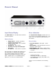

DAC1 HDR
Instruction Manual Rev I Page 16
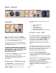
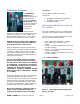
Output Level Switch
The Output Level Switch is a
three-position toggle switch
located on the rear panel. The
DAC1 HDR ships with this
switch set in the Variable
position.
CAUTION: Do not set the ‘Output Level’
switch to ‘Calibrated’ if the DAC1 HDR is
directly connected to a power amplifier
or powered speakers. The ‘Calibrated’
will produce a high-level output that may
be too loud for your speakers.
Calibrated (UP) – Analog output levels are
controlled by 10-turn internal trim controls. A
full description of the calibration trim controls
and instructions for configuration is located in
the Internal Setting section of this manual.
Off (CENTER) – Analog XLR and RCA outputs
are muted; headphone outputs remain active.
Variable (DOWN) – Analog output levels are
controlled by the Volume Control.
The Output Level Switch does not affect the
operation of the headphone jacks (the
headphone outputs are never disabled and
the headphone level is always controlled from
the Volume Control).
TIP: If the DAC1 HDR is being used in a
critical signal chain (such as a broadcast
facility or theater) the headphone mute
switch should be defeated using the
internal jumpers. See ‘Internal Settings’
section for instructions.
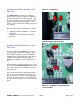
Balanced XLR Analog Line
Outputs
The Left and Right balanced outputs use
Neutrik™ gold-pin male XLR jacks. The XLR
shell and pin 1 (ground) are both directly
bonded to the chassis to prevent currents in
the internal ground systems. This direct
bonding also maximizes RF shielding.
The XLR output levels may be controlled from
the front panel, or may be set to fixed levels
using the internal Calibration Trimmers. A
full description of the calibration trim controls
and instructions for configuration is located in
the Internal Setting section of this manual.
The XLR outputs have passive attenuators
that allow direct connections to a wide variety
of audio devices without a loss of dynamic
range. The 20 dB pad is usually required for
direct interfacing to power amplifiers and
powered speakers. The DAC1 HDR ships
with the 20 dB pad enabled. A full description
of the output attenuators and instructions for
configuration is located in the Internal
Setting section of this manual.
Industry-standard XLR wiring:
XLR pin 2 = + Audio Out
XLR pin 3 = - Audio Out
XLR pin 1 = Cable Shield
CAUTION: If the balanced XLR outputs
are wired to an unbalanced input (using
a special adapter cable), pin 3 must be
left floating. Shorting pin 3 to ground
will increase the temperature of the
output drivers, will increase power
consumption, and may cause distortion.