
Instruction manual
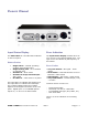

DAC1 HDR
Instruction Manual Rev I Page 19
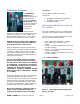
Calibration Trimmers
The Calibration
Trimmers are
located internally on
the circuit board
behind the Output
Level Switch. They
are 10-turn trimmers
and are adjustable
using a small
screwdriver.
These trimmers
provide a 2 dB per rotation adjustment with a
total control range of + 9 to +29 dBu at 0
dBFS (full-scale digital input). There are no
stops at either end of the 10-turn rotation.
CAUTION: Do not change the calibration
trimmers unless you have the ability to
accurately measure audio levels.
Factory calibration has been set so that the
output level at the balanced XLR connectors is
+4 dBu at -0 dBFS. This is exactly 20 dB
lower than a typical alignment of +4 dBu at
-20 dBFS. The lower level is appropriate for
most powered monitors.
TIP: To set the XLR outputs to typical
professional studio levels, set the pads
to 0 dB, and set the ‘Output Level Switch’
to ‘Calibrated’. If the factory settings of
the ‘Calibration Trimmers’ have not been
changed, the XLR outputs will be
calibrated to +4 dBu at -20 dBFS, and the
RCA outputs will be calibrated to -10 dBV
at -16 dBFS.
The factory-preset levels may be increased by
5 dB or decreased by 15 dB in order to
conform to other studio reference levels. This
range of levels is also well suited for direct
connection to the balanced line-level inputs
on most power amplifiers. Most professional
equipment will work well at these levels.
Note: The Calibration Trimmers have no
effect on the output levels when the
Output Level Switch is set to Variable.
Jumpers
The following functions are jumper
configured:
•
Headphone Gain Range Adjustment
•
Headphone Switch Disable
•
XLR Output Pads
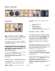
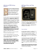
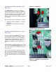
XLR Output Pad Selection (P5, P6,
P7, and P8):
Four 8-pin headers (P5, P6, P7, and P8) allow
selection of the output level at the XLR jacks.
One pair of 8-pin headers controls the output
level at each XLR jack as follows:
•
0 dB - (Attenuator disabled) – (Jumper
plug between pins 1 and 2 of each
header)
•
-10 dB – (Jumper plug between pins 3 and
4 of each header)
•
-20 dB – ***(Jumper plug between pins 5
and 6 of each header)
•
-30 dB – (Jumper plug between pins 7 and
8 of each header)
*** = Factory Default
Photo 1 - XLR Output Pad Selection (P5,
P6, P7, and P8)