
Technical data
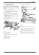
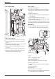
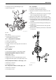

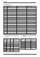

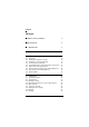
Table Of Contents

6 720 611 449 GB (03.11)
Maintenance
41
9.3 Replacement of Parts
Before changing any components check that the gas is
turned off and that the appliance is electrically isolated.
When necessary close the system valves and drain the
appliance.
Refitting is a reverse of the procedure for removal using
new seals or o-rings as appropriate.
9.3.1 PCB control board and transformer
B Switch off the appliance.
B Disconnect appliance from the power supply.
B Unplug all connectors from the control box (inc.
keyed plug). Access is gained by removing the cov-
ers. Refer to fig. 25, 26.
B Remove screw holding power connector earth lead
and remove earth lead.
B Remove two top fixing screws from the control box.
Refer to fig. 54.
Fig. 54
B Lower the control box.
B Unscrew earth lead.
B Unscrew four fixing screws from cover plate. Refer to
fig. 55.
B Prise off cover plate.
B Pull off transformer.
B Remove pcb holder.
B Remove the pcb control board.
Fig. 55
Fuses
B Remove the connections covers. Refer to fig. 25,
26.
The fuses are located adjacent to the mains connector
block and connector ST18. Refer to fig. 4.
Fuse, item 312, is only replaceable by removing the
pcb.
Spare fuses are fixed to the connections cover.
A fuse pack is available: Part number 8 744 503 010 0.
7
181 465 330-09.1R
1
2
3
4
5
E
1
3
2
4
1
3
2
4
1
3
2
4
7 181 465 330-10.1
R