
Technical data
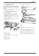
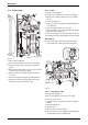
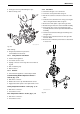
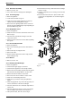


Table Of Contents
6 720 611 449 GB (03.11)
Maintenance
43
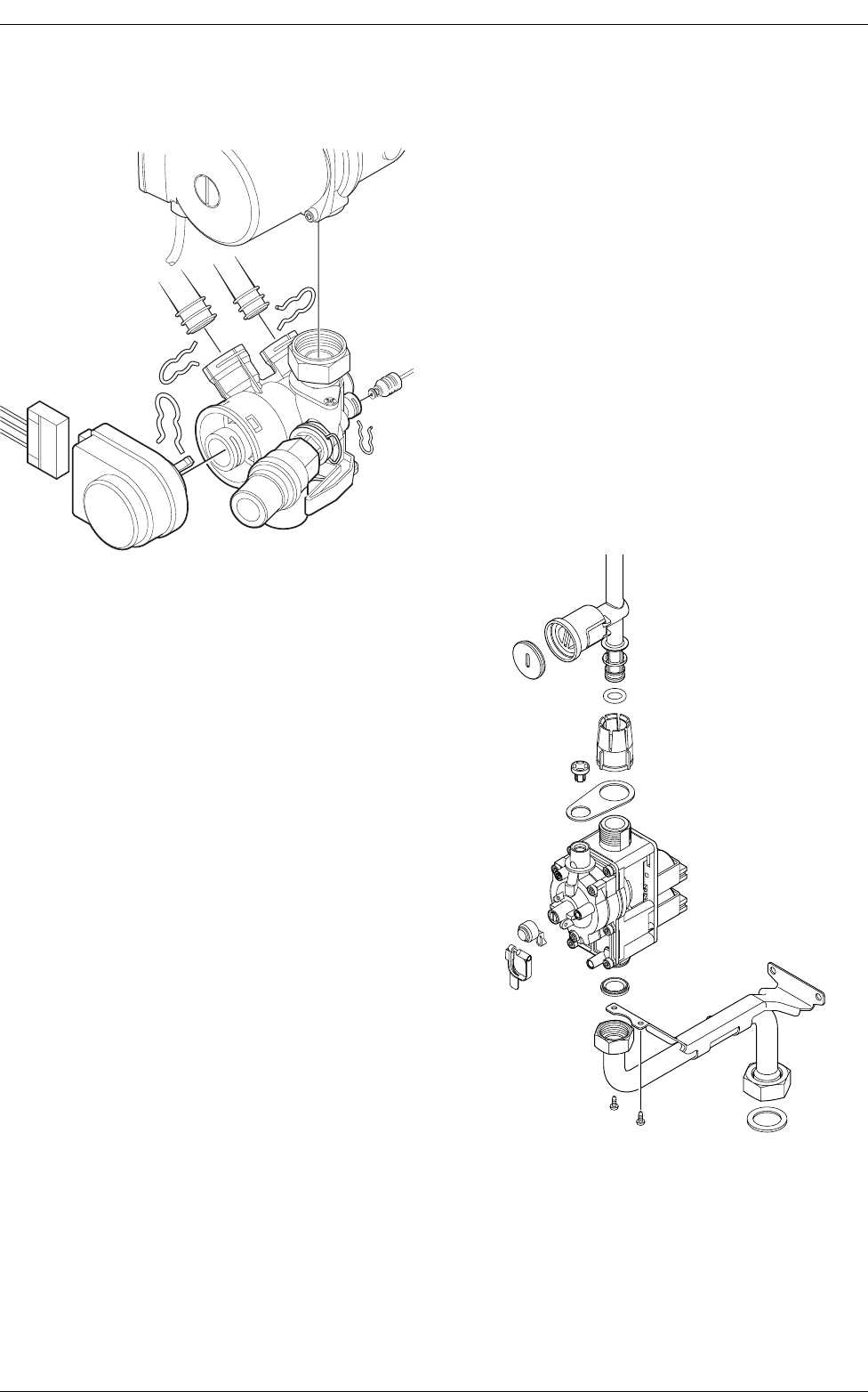
B Undo pipe unions by withdrawing the clips.
B Remove 3-way valve.
Fig. 58
After refitting:
B Fill system, bleed and re-pressurise
(see Installation Instructions).
9.3.5 3-way diverter valve motor
B Switch off the appliance.
B Turn off the service cocks.
B Unplug connector from 3-way valve motor. Refer to
fig. 58.
B Pull out retaining clip.
B Remove motor.
9.3.6 Sensors
B Check that the appliance is electrically isolated.
Central Heating Flow Temperature Sensor –
Item 36, fig. 2, 54
B Pull-off the connector.
B Release the sensor clip and withdraw the sensor.
B Apply heat transfer paste to the replacement sensor.
Safety Temperature Limiter – Item 6, fig. 2, 54
B Pull-off the connectors.
B Unscrew the sensor.
Flue Temperature Limiter – Item 9, fig. 2, 54
B Pull-off the connectors.
B Unscrew the sensor.
9.3.7 Gas Valve
B Check that the gas cock is turned off.
B Lower the control panel. Refer to fig. 57.
B Pull off the solenoid connections at the rear of the
valve.
B Undo the union, within the inner casing, securing the
valve to the gas/air tube. Refer to fig. 56.
B Remove the white plastic cap from the gas valve.
B Release the gas inlet union at the manifold assembly.
B Unscrew the two screws securing the gas valve
assembly bracket to the back panel and withdraw the
assembly.
B Transfer the bracket and inlet pipe assembly to the
new gas valve.
B Check for gas soundness when the new gas valve
has been fitted.
B Recheck the combustion performance as described
in section 8.1.
Fig. 59
7 181 465 330-12.1
R
6 720 610 602 - 04.1O