
Technical data

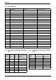
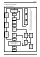

Table Of Contents
6 720 611 449 GB (03.11)
Appendix
47
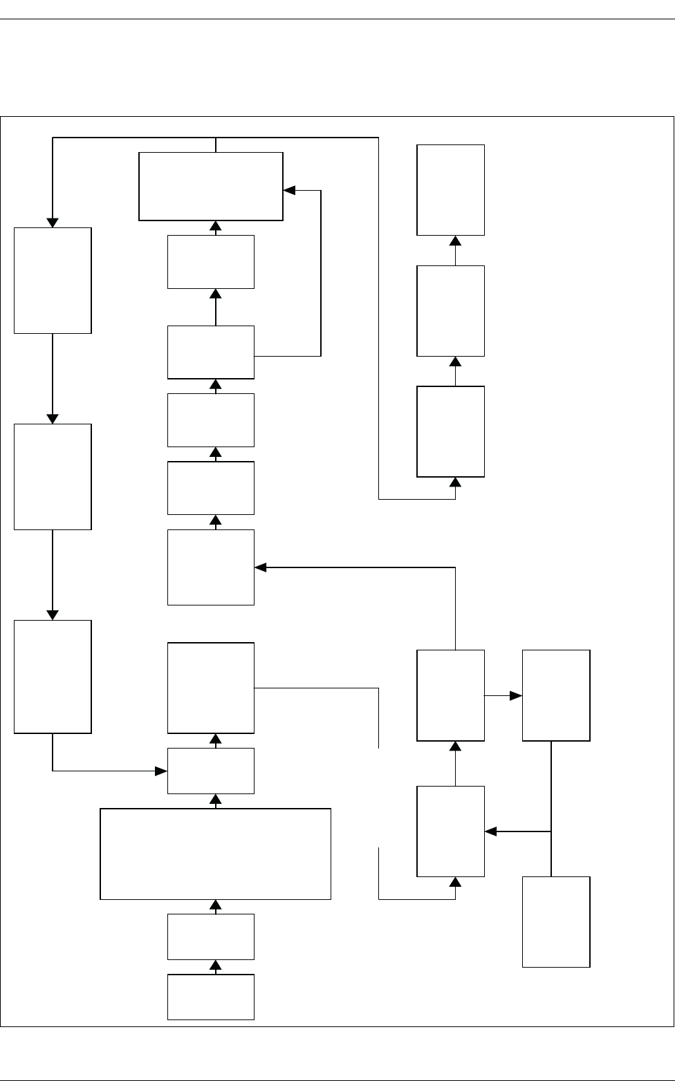
10.5 Operational Flow diagrams
10.5.1 Central heating function
Fig. 61
6 720 610 576 - 26.TD
Yes
No
Yes
No
Mains
switch
ON.
Green
light
ON.
Room
thermostat
and/or mains
programmer or
link ON AND
Electronic facia
programmer (if
fitted) ON AND
CH control
knob ON.
CH
demand.
Burner remains OFF
until flow temperature
is below set value.
Gas valve shuts.
Pump remains ON.
Over temperature
shut down if water
temperature is 5°C
above set value.
Pump ON Fan to
start speed. Gas
valve opens.
Burner
stabilises at
start speed for
5-10 secs
Fan speed
reduces
over 15
secs.
Fan min.
speed for
90 secs.
Boiler
unused
for long
period.*
*Minimum
heat
input for
15min.
Boiler
operates to
match
system load
and CH
control
setting.
Ignition sequence
Ignition spark for
5 seconds.
Burner lights. Red
light ON.
Repeats 5 times
(N.G.) or 3 times
(L.P.G.) before
lock-out.
Fan runs to
purge gas from
burner.
CH demand
satisfied.
Gas valve closes.
Red light OFF.
Pump and Fan
run for up to 3
mins.
* NOTE: The sequence ensures that the condensate siphon is not empty
after long
OFF periods. (More than 24 hours without a demand).