SD-08-2414 Bendix® AD-IP™ Integral Purge Air Dryer DESICCANT CARTRIDGE SADDLE MOUNTING BRACKET MOUNTING STRAP SAFETY VALVE SAFETY VALVE CONTROL PORT LOWER MOUNTING BRACKET CONTROL PORT HEATER & THERMOSTAT CONNECTOR SUPPLY PORT HEATER & THERMOSTAT CONNECTOR SUPPLY PORT FIGURE 1 - AD-IP™ INTEGRAL PURGE AIR DRYER DESCRIPTION The AD-IP™ air dryer has three female pipe thread air connections identified as follows: The function of the Bendix® AD-IP™ integral purge air dryer is to collect and remove
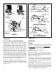
DISCHARGE LINE SUPPLY RES. HOLSET COMPRESSOR FIGURE A HOLSET TYPE E & QE COMPRESSORS - NO AIR DRYER FEEDBACK LINE STANDARD AD-IP™ AIR DRYER SPECIAL DISCHARGE PORT FTG. W/ FEEDBACK LINE CONNECTION CHECK VALVE SUPPLY RES. HOLSET COMPRESSOR DISCHARGE PORT FIGURE B STANDARD AD-IP™ AIR DRYER AND HOLSET TYPE E & QE COMPRESSORS LOWER MTG. BRKT. (PARTIAL) SPECIAL DISCHARGE PORT FTG.
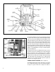
OIL SEPARATOR DESICCANT BED PURGE ORIFICE PURGE VOLUME CONTROL PORT PURGE CONTROL LINE SUPPLY PORT GOVERNOR COMPRESSOR ENGINE TURBO TURBO CUTOFF VALVE PURGE VALVE EXHAUST DELIVERY CHECK VALVE (OLD STYLE SHOWN) DISCHARGE PORT FIGURE 4 - AD-IP™ INTEGRAL PURGE AIR DRYER CHARGE CYCLE Air, along with the remaining water vapor, is further cooled as it exits the oil separator and continues to flow upward between the outer and inner shells.
OIL SEPARATOR DESICCANT BED PURGE ORIFICE PURGE VOLUME CONTROL PORT PURGE CONTROL LINE SUPPLY PORT GOVERNOR COMPRESSOR ENGINE TURBO TURBO CUTOFF VALVE PURGE VALVE EXHAUST DELIVERY CHECK VALVE (OLD STYLE SHOWN) DISCHARGE PORT FIGURE 5 - AD-IP™ INTEGRAL PURGE AIR DRYER PURGE CYCLE PURGE VOLUME CONTROL PORT SUPPLY PORT TURBO CUTOFF VALVE PURGE VALVE FIGURE 6 - AD-IP™ INTEGRAL PURGE AIR DRYER TURBO CUTOFF The actual reactivation of the desiccant drying bed begins as dry air flows from the purge
DESICCANT BED SPRING OIL SEPARATOR DESICCANT CARTRIDGE PURGE ORIFICE PIPE PLUG PURGE VOLUME CONTROL PORT CHECK VALVE (BLACK) SUPPLY PORT DELIVERY PORT TURBO CUTOFF VALVE O-RING PURGE VALVE CARTRIDGE BOLT DELIVERY PORT CARTRIDGE BOLT Old Style End Cover -Vertical Delivery Check Valve CHECK VALVE (WHITE) New Style End Cover - Horizontal Delivery Check Valve FIGURE 7 - AD-IP™ AIR DRYER SECTIONAL VIEW connected to the engine turbocharger.
Note: A small amount of oil in the system is normal and should not be considered as a reason to replace the desiccant cartridge; oil stained desiccant can function adequately. 2. Visually check for physical damage to the AD-IP™ air dryer such as chaffed or broken air and electrical lines and broken or missing parts. 3. Check mounting bolts for tightness. Re-torque to 270- 385 in.lbs. 4. Perform the Operation & Leakage Tests listed in this publication.
A. Electric Power to the Dryer With the ignition or engine kill switch in the ON position, check for voltage to the heater and thermostat assembly using a voltmeter or test light. Unplug the electrical connector at the air dryer and place the test leads on each of the pins of the connector with the locking latch. If there is no voltage, look for a blown fuse, broken wires, or corrosion in the vehicle wiring harness. Check to see if a good ground path exists. 109498 .........................................
all reservoirs before beginning ANY work on the vehicle. If the vehicle is equipped with an AD-IS® air dryer system or a dryer reservoir module, be sure to drain the purge reservoir. 5. Following the vehicle manufacturer’s recommended procedures, deactivate the electrical system in a manner that safely removes all electrical power from the vehicle. 6. Never exceed manufacturer’s recommended pressures. 7. Never connect or disconnect a hose or line containing pressure; it may whip.
8. Vertical check valve models: Remove the retaining ring (25) that secures the delivery check valve assembly in the end cover (6). Remove and separate the perforated plate (26), spring (27), check valve body (28) and o-ring (29). 2. Install and center the exhaust diaphragm (17) over the shoulder bolt (16) making certain that the diaphragm ID is over the bolt shoulder. Then install the purge valve (18) on the shoulder bolt making certain its metal support side is against the diaphragm (17). 9.
11 1 4 5 3 6 33 32 31 30 9 34 35 36 2 21 12 13 20 8 22 7 23 10 15 24 21 20 22 19 18 24 17 16 19 14 18 17 16 15 14 DLU Style Purge Valve FIGURE 9 - AD-IP™ AIR DRYER INTERNAL COMPONENTS 10
ITEM# DESCRIPTION 1 2 5/16” Cap Screw O-ring 3 4 5/16” Sleeve Nut Mounting Strap 5 6 Saddle Bracket End Cover 7 8 3/8” Cap Screw 3/8” Lock Washer 9 10 Lower Mounting Bracket Cartridge Bolt 11 12 Desiccant Cartridge O-ring 13 14 O-ring Retaining Ring 15 16 Purge Valve Cartridge Assembly Shoulder Bolt 17 18 Exhaust Diaphragm Purge Valve 19 20 Purge Valve Housing Purge Valve Piston 21 22 Quad Ring Piston Return Spring 23 24 O-ring O-ring 25 26 27 Retaining Ring Perforated Plate Check R
10. Install the desiccant cartridge (11) on the end cover (6) making certain the cartridge is properly seated and flush on the end cover. Note: It may be necessary to rotate the cartridge slightly until the anti-rotation lugs are properly aligned and allow the cartridge to rest flush against the end cover. 11. Using an adjustable wrench or a socket, tighten the desiccant cartridge bolt (10), to secure the desiccant cartridge (11) to the end cover (6). Torque the desiccant cartridge bolt to 65-75 ft. lbs.
CFM that an authorized Bendix parts outlet or Bendix marketing representative be contacted for assistance. Holset “E or QE” Type Air Compressors - In order for these Holset compressors to function properly when installed with an AD-IP™ air dryer, the required Holset feedback line and single check valve must be used. The standard AD-IP™ air dryer can be used with a separate feedback line and single check OR the AD-IP™ DI (Drop In) air dryer model can be used.
PURGE EXHAUST LINE 1. If it is necessary to direct AD-IP™ air dryer discharge contaminants away from vehicle components it will be necessary to purchase a special exhaust cover for the AD-IP™ air dryer (Pc. No. 112609) and install on the unit. A 1” (25.4 mm) I.D. hose can be clamped on the special AD-IP™ air dryer exhaust cover. GOVERNOR AD-IP™ AIR DRYER WIRING THE HEATER/THERMOSTAT 1. The air dryer is available with either a 12 or 24 volt heater which uses 90 watts of power.
FRAME RAIL STAR WASHER 1/4" or 3/8" EYELET NUT GROUND LEAD WEATHERPROOF POWER LEAD SPLICE 14 GAGE POWER WIRE FROM VEHICLE WIRE HARNESS CONNECTOR (TO AIR DRYER) FIGURE 11 - WIRING - REMOTE POWER & LOCAL GROUND TESTING THE AD-IP™ AIR DRYER Before placing the vehicle in service, perform the following tests. 1. Close all reservoir drain cocks. 2. Build up system pressure to governor cutout and note that the AD-IP™ air dryer purges with an audible escape of air. 3.
AD-IP™ AIR DRYER TROUBLESHOOTING CHART SYMPTOMS 1. Dryer is constantly “cycling” or purging. Dryer purges frequently (every 4 minutes or less while vehicle is idling). CAUSE A. Excessive system leakage. IMPORTANT: Note whether air pressure loss is shown on dash gauge(s). Pressure loss shown on gauges is caused by service brake system or component leakage. Pressure loss NOT SHOWN on gauges is caused by supply system or component leakage. REMEDY A.
AD-IP™ AIR DRYER TROUBLESHOOTING CHART (Continued) SYMPTOMS 1. Dryer is constantly “cycling” or purging. Dryer purges frequently (every 4 minutes or less while vehicle is idling) (continued). CAUSE REMEDY 1. Test fittings, hoses, lines and connections. Apply soap solution to detect excessive leakage. Tighten or replace as needed then repeat the air dryer charge-purge cycle and observe the gauge installed in the supply reservoir.
AD-IP™ AIR DRYER TROUBLESHOOTING CHART (Continued) SYMPTOMS CAUSE REMEDY 6. With gauge installed at RES port of governor, pressure should not drop below ”Cut-In” pressure at the onset of the compressor “Unloaded” cycle. If pressure drops, check for “kinks” or restrictions in line connected to RES port. Line connected to RES port on governor must be same diameter, or preferably larger than, lines connected to UNL port(s) on governor. 1. Dryer is constantly “cycling” or purging.
AD-IP™ AIR DRYER TROUBLESHOOTING CHART (Continued) SYMPTOMS 2. Water and/or Oil in Supply or Service Reservoir (continued). CAUSE D. Purge (air exhaust) time insufficient due to excessive system leakage (see causes for Symptom #1). REMEDY D. Check causes and remedies for Symptom #1. E. Excessive air usage, duty cycle too high - Air dryer not compatible with vehicle air system requirement (Improper air dryer/vehicle application). E. See Appendix A, Table A, column 1, for recommended compressor sizes.
AD-IP™ AIR DRYER TROUBLESHOOTING CHART (Continued) SYMPTOMS CAUSE REMEDY Discharge Line Freeze-Up. The discharge line must maintain a constant slope down from the compressor to the air dryer inlet fitting to avoid low points where ice may form and block the flow. If, instead, ice blockages occur at the air dryer inlet, insulation may be added here, or if the inlet fitting is a typical 90 degree fitting, it may be changed to a straight or 45 degree fitting.
AD-IP™ AIR DRYER TROUBLESHOOTING CHART (Continued) SYMPTOMS REMEDY CAUSE When replacing the desiccant cartridge, make sure desiccant cartridge assembly is properly installed and sealing rings are in place on mounting surface of desiccant cartridge. 2. Water and/or Oil in Supply or Service Reservoir (continued). Check Valve Feedback Line Typical Drop-In Air Dryer End Cover I. Desiccant requires replacement. I. Replace desiccant cartridge assembly.
AD-IP™ AIR DRYER TROUBLESHOOTING CHART (Continued) SYMPTOMS 4. Safety valve on air dryer “popping off” or exhausting air (continued). 5. Constant exhaust of air at air dryer purge valve exhaust. (Charge mode.) CAUSE F. Governor malfunction. Missing or restricted governor control line installation. F. Test governor operation and/or inspect the control line leading from the governor UNL (unloader) port to the air dryer control port. A. Air dryer purge valve leaking excessively. A.
AD-IP™ AIR DRYER TROUBLESHOOTING CHART (Continued) SYMPTOMS CAUSE REMEDY 8. Desiccant material being expelled from air dryer purge valve exhaust (may look like whitish liquid or paste or small beads.) A. This symptom is almost always accompanied by one or more of Symptoms 1, 2, 3, 4 and 5. See related causes for these symptoms above. A. See Causes and Remedies for Symptoms 1, 2, 3, 4 and 5. B. Air dryer not securely mounted. (Excessive vibration.) B. Vibration should be held to minimum.
Appendix A Table A: Maintenance Schedule and Usage Guidelines Regularly scheduled maintenance is the single most important factor in maintaining the air brake charging system. Vehicle Used for: No. of Axles Column 1 Column 2 Typical Compressors Spec'd Discharge Line I.D. Length 1/2 in. 6 ft.
Appendix B Additional Troubleshooting Information The troubleshooting procedure presented on the following pages has been excerpted from a laminated card entitled: Troubleshooting Charging and Air Supply Systems. The complete card can be obtained from authorized Bendix parts outlets under literature number BW1779. It is presented here because of the air dryers connection to the supply air system and for convenience.
COMPLAINTS COMMON TO THE CHARGING & AIR SUPPLY SYSTEM Complaint: Can Not Build System Pressure • Discharge line plugged or restricted: see Common Test 1. • Air pressure trapped between governor and compressor unloaders: see Common Test 2. • Blow leakage at air dryer exhaust: see Common Test 3. Complaint: Air System Builds Too Slow • Discharge line restricted: see Common Test 1. • Discharge line leakage: see Common Test 5. • Air leaking at air dryer exhaust: see Common Test 3.
TESTS COMMON TO MORE THAN ONE COMPLAINT 1. Discharge plugged or restricted • Connect temporary discharge line from comp. discharge port to supply res. & re-check build-up. If build-up OK replace plugged discharge line. If build-up NOT OK go to next cause. 2. Air pressure trapped between governor and compressor • Verify safety valve operation then remove or disconnect governor from compressor & check build-up. • If build-up OK, repair or replace governor or line between governor and compressor.
BW1811 © 2007 Bendix Commercial Vehicle Systems LLC All rights reserved. 5/2007 Printed in U.S.A.