
Owner manual


7
the maintenance kit should always be used in lieu of
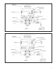
those presented here. Refer to Figure 6 throughout the
disassembly and assembly procedure.
CAUTION: The AR-1
™
valve may be lightly clamped in a
bench vise during disassembly, however, over clamping
will cause damage to the valve and result in leakage and/
or malfunction. If a vise is to be used, position the valve so
that the jaws bear on the supply ports on opposing sides
of the valve’s body.
1. Remove all air fi ttings and plugs from the valve.
2. Mark the relationship of the antilock electronic controller
and valve cover to the body (5). Note the position of
the mounting bracket and mark the relationship of the
bracket to the valve body, cover, and antilock controller.
Remove and retain the four cap screws and lock
washers (1) that secure the controller to the cover (15),
then carefully remove the electronic controller without
damaging its gasket (2).
3. While holding the exhaust cover (4), remove and
discard the retaining ring (3) that secures it to the body
(5).
4. Remove and discard the exhaust cover (4) along with
both o-rings (6 & 7).
5. Remove and discard the valve spring (8), valve retainer
(9), and the valve assembly (10) from the body (5).
6. Remove and retain the two cap screws (11) and lock
washers (12) that secure the cover (15) to the body (5).
Remove and retain the two bolts (13), lock washers
(12), and nuts (14) that secure the cover (15) and
mounting bracket to the valve body (5).
7. Separate the cover (15) and mounting bracket from
the body (5), then remove and discard the sealing
ring (16). Remove and retain the two cap screws and
lockwashers (26) that secure the bracket to the cover
(15).
8. Remove and retain the relay piston (17) and relay piston
spring (19) from the body (5). NOTE: The relay piston
spring, item 19 is not used in all valves.
9. Remove and discard the o-ring (18) from the relay
piston (17).
10. Remove and retain the service port cap nut (20) from
the cover (15), then separate and discard the cap nut
o-ring (21) from the cap nut.
11. Remove and discard the quick exhaust diaphragm (22)
from the cover (15).
12. Remove the quick exhaust diaphragm retaining screw
(23), the diaphragm washer (24) and the diaphragm
(25) from the cover (15).
CLEANING & INSPECTION
1. Using mineral spirits or an equivalent solvent, clean
and thoroughly dry all metal parts.
2. Inspect the interior and exterior of all metal parts that
will be reused for severe corrosion, pitting and cracks.
Superfi cial corrosion and/or pitting on the exterior
portion of the body (5) and cover (15) is acceptable.
Replace the entire valve if the interior of the body or
cover exhibit signs of corrosion or pitting.
3. Inspect the bores of both the body (5) and cover (15)
for deep scuffi ng or gouges. Replace the entire valve
if either are found.
4. Make certain all air channels and exhaust passages in
the valve cover (15) are clear and free of obstruction.
5. Inspect the pipe threads in the body (5). Make certain
they are clean and free of thread sealant.
6. Wash all non-metallic components in a soap and water
solution making certain to rinse and dry thoroughly.
Inspect each non-metallic component for cracks, wear
or distortion. Replace the entire valve if these conditions
are found.
7. If the valve was equipped with a relay piston spring
(19), inspect it for signs of corrosion, pitting and cracks.
Replace as necessary.
8. Inspect all air line fi ttings for corrosion and replace
as necessary. Make certain to remove all old thread
sealant before reuse.
ASSEMBLY
1. Prior to assembly, lubricate all o-rings, seals, and
pistons, as well as body bores, using the lubricant
provided with the Bendix maintenance kit.
2. Install the valve retainer (9) on the inlet and exhaust
valve (10) so that the fl ange of the retainer (9) surrounds
the rubber portion of the valve. Install the inlet and
exhaust valve in the body (5).
3. Install the inlet and exhaust valve return spring (8) in
the body (5).
4. Install the large and small diameter o-rings (7 & 6) in
the exhaust cover (4), then install the exhaust cover
in the body (5) taking care not to damage the o-rings.
Hold the exhaust cover in place.
5. While depressing the exhaust cover (4), install the
retaining ring (3) in the body (5). Make certain the
retainer (3) is fully seated in its groove in the body.
6. If the AR-1
™
valve was equipped with a relay piston
return spring (19), install the spring in the body, large
diameter fi rst.
7. Using lubricant to hold them in place, install sealing
ring (16) on the cover (15).