
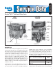
Owner manual


8
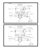
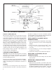
8. Install the o-ring (18) on the relay piston (17), then install
the piston in the body (5).
9. After noting the relationship marks made prior to
disassembly, assemble the cover (15) on the body (5)
and the mounting bracket on the body (5) and secure
the components together using the two cap screws
(11) and two bolts (13), lock washers (12), and nuts
(14). Torque the cover cap screws (11) and bolts (13)
to 120-150 lb. in.
10. Install the two cap screws and lock washers (26) that
secure the bracket to the cover (15) and torque them
to 180-220 lb. in.
BW1665 © 2011 Bendix Commercial Vehicle Systems LLC. All Rights Reserved. 01/11 Printed in U.S.A.
11. After noting the relationship of marks made prior to
disassembly, attach the gasket (2) to the antilock
controller then secure the antilock controller on the
cover (15) using the four cap screws and lock washers
(1). Torque the cap screws to 50-80 lb. in.
12. Install all air line fi ttings and plugs making certain thread
sealing material does not enter the valve.
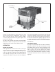
13. Install the CR-15 (AR-1
™
valve with attached antilock
controller) on the vehicle and perform the Operation and
Leakage Tests before returning the vehicle to service.