
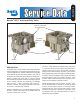
Owner manual

10
DISASSEMBLY
GENERAL
The following disassembly and assembly procedure is
presented for reference purposes only and presuppos‑
es that the appropriate maintenance kit is on hand at
the time of disassembly. The instructions provided with
the maintenance kit should always be used in lieu of
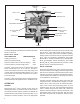
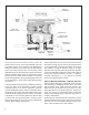
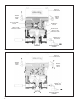
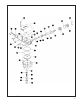
those presented here. Refer to gure 10 throughout the
disassembly and assembly procedure. CAUTION: The
Bendix
®
AR‑2
™
valve may be lightly clamped in a bench
vise during disassembly, however, over clamping will
cause dam age to the valve and result in leakage and/or
malfunc tion. If a vise is to be used, position the valve so
that the jaws bear on the supply ports on opposing sides
of the valve’s body.
1. Remove all air ttings and plugs from the AR‑2
™
valve.
2. Mark the relationship of the antilock electronic controller
(2) and valve cover (4) to the body (9). Note the position
of the mounting bracket (6) and mark the relationship
of the bracket to the valve body (9), cover (4), and
antilock controller (2). Remove and retain the four cap
screws and lock washers (1) that secure the controller
to the cover (4), then carefully remove the electronic
controller without damaging its gasket (3).
3. While holding the exhaust cover (11), remove the
retaining ring (10) that secures it to the body (9).
4. Remove the exhaust cover (11) along with both o‑rings
(12 & 13).
5. Remove the valve spring (14), valve retainer (15), and
the valve assembly (16) from the body (9).
6. Remove and retain the two cap screws and lock washers
(5) that secure the bracket (6) to the cover (4). Remove
and retain the two bolts with lock washers (7), and nuts
(8) that secure the cover (4) and mounting bracket to
the valve body (9). Then remove the remaining two cap
screws (7) that secure the cover (4) to the body (9).
7. Separate the cover (4) and mounting bracket (6) from
the body (9), then remove the large and small sealing
rings (19 & 40).
8. Remove and retain the relay piston (17) and relay piston
spring (if present) from the body (9). NOTE: The relay
piston spring is not used in all AR‑2
™
valves.
9. Remove the o‑ring (18) from the relay piston (17).
10. Remove the retaining ring (20) from the cover (4), then
remove the exhaust piston (21).
11. Remove the exhaust piston o‑ring (22).
12. Remove the service piston (23) from the cover (4).
13. Remove the spring (24) and spring cage (25) from the
cover (4).
14. Remove the blend back piston (26) from the valve cover
(4), then remove both o‑rings (27 & 28).
15. Remove the proportioning piston (30) from the valve
cover (4), then remove both o‑rings (29 & 31).
16. While holding the inlet valve seat (34) in place, remove
the retaining ring (36) from the proportioning piston
(30).
17. Remove the inlet valve seat (34), the inlet valve (33),
and the valve spring (32) from the proportioning piston
(30), then remove the o‑ring (35) from the valve seat
(34).
18. Remove the exhaust diaphragm screw (37), washer
(38) and exhaust diaphragm (39) from the cover (4).
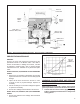
CLEANING & INSPECTION
1. Using mineral spirits or an equivalent solvent, clean
and thoroughly dry all metal parts.
2. Inspect the interior and exterior of all metal parts that
will be reused for severe corrosion, pitting and cracks.
Supercial corrosion and/or pitting on the exterior
portion of the body (9) and cover (4) is acceptable.
Replace the entire valve if the interior of the body or
cover exhibit signs of corrosion or pitting.
3. Inspect the bores of both the body (9) and cover (4)
for deep scufng or gouges. Replace the entire valve
if either are found.
4. Make certain all air channels and exhaust passages in
the valve cover (4) are clear and free of obstruction.
5. Inspect the pipe threads in the body (9). Make certain
they are clean and free of thread sealant.
6. Wash all non‑metallic components in a soap and water
solution making certain to rinse and dry thoroughly.
Inspect each non‑metallic component for cracks, wear
or distortion. Replace the entire valve if these conditions
are found.
7. If the valve was equipped with a relay piston spring,
inspect it for signs of corrosion, pitting and cracks.
Replace as necessary.
8. Inspect all air line ttings for corrosion and replace
as necessary. Make certain to remove all old thread
sealant before reuse.
ASSEMBLY
1. Prior to assembly, lubricate all o‑rings, seals, and
pistons, as well as body and cover bores, using the
lubricant provided with the Bendix maintenance kit.
2. Install the o‑ring (35) on the inlet valve seat (34).
3. Insert the inlet and exhaust valve spring (32), LARGE
END FIRST, into the proportioning piston (30).
4. Install the inlet and exhaust valve (33) inside the inlet
valve seat (34) making certain that the four tabs are
within the bore of the seat.