
Owner manual


11
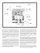
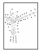
5. Carefully insert the assembled valve (33) and seat (34)
into the proportioning piston (30), making certain that
the coils of the valve spring (32) rest on the four tabs
of the valve (33). While holding the seat (34) in place,
install the retaining ring (36) to secure it in the piston
(30). Make certain the retaining ring is fully seated in
its groove.
6. Install both the large and small diameter o‑rings (31 &
29) on the proportioning piston (30).
7. Install both the large and small diameter o‑rings (27 &
28) on the blend back piston (26), then insert the small
diameter of the proportioning piston (30) into the small
diameter end of the blend back piston (26).
8. Carefully insert the assembled proportioning and blend
back pistons (30 & 26) into the cover (4).
9. Install the spring cage (25) in the blend back piston (26)
so that its at side rests against the blend back piston.
10. Install the spring (24) in the cage (25) so that its coils
are within the I.D. of the cage.
11. Insert the service piston (23) in the cover (4) so that the
coils of the spring (24) are contained within the piston
and the six protruding posts of the piston are visible
after the piston is in the cover.
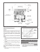
12. Install the o‑ring (22) on the exhaust piston (21) then
install the exhaust piston (21) in the cover (4). Refer
to the gure and make certain that the exhaust piston
(21) is installed with its concave surface away from the
service piston (23).
13. While holding the exhaust piston (21) in the cover (4),
install the retaining ring (20), making certain it is fully
seated in its groove.
14. Install the exhaust diaphragm (39) using its screw (37)
and washer (38) to retain it. Torque the screw to 8‑15
pound inches.
15. Install the valve retainer (15) on the inlet and exhaust
valve (16) so that the flange of the retainer (15)
surrounds the rubber portion of the valve. Install the
inlet and exhaust valve in the body (9).
16. Install the inlet and exhaust valve return spring (14) in
the body (9).
17. Install the large and small diameter o‑rings (13 & 12)
in the cover (11), then install the exhaust cover in the
body (9) taking care not to damage the o‑rings. Hold
the exhaust cover in place.
18. While depressing the exhaust cover (11), install the
retaining ring (10) in the body (9). Make certain the
retainer (10) is fully seated in its groove in the body.
19. If the Bendix
®
AR‑2
™
valve was equipped with a relay
piston return spring, install the spring in the body, large
diameter rst.
20. Using lubricant to hold them in place, install the large
diameter sealing ring (19) on the cover (4) and the small
diameter sealing ring (40) on the body (9).
21. Install the o‑ring (18) on the relay piston (17), then install
the piston in the body (9).
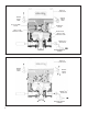
22. After noting the relationship marks made prior to
disassembly, install the cover (4) on the body (9).
Secure the cover to the body using the two shortest cap
screws and lock washers (7). Make certain the sealing
rings (19 & 40) remain in place. Torque the cap screws
to 120‑150 pound inches.
23. Secure the mounting bracket (6) to the cover (4) using
the cap screws and lock washers (5), and torque the
cap screws to 180‑220 pound inches. Then secure the
mounting bracket (6) to the body (9) and cover (4) using
the two longest cap screws and lock washers (7) and
nuts (8) and torque the cap screws to 120‑150 pound
inches.
24. Install all air line ttings and plugs making certain thread
sealing material does not enter the valve.
25. Install the AR‑2
™
valve on the vehicle and perform
the Operation and Leakage Tests before returning the
vehicle to service.
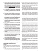
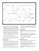
O.D.
W
I.D.
KEY NO. I.D. O.D. W
12 .862" 1.068" .103"
13 1.424" 1.630" .103"
19 3.487" 3.693" .103"
18 3.234" 3.512" .139"
22 1.356" 1.496" .070"
27 1.112" 1.318" .103"
28 .737" .943" .103"
29 .412" .552" .070"
31 .739" .879" .070"
35 .489" .629" .070"
O-RING IDENTIFICATION CHART