
Owner manual


7
2. Stop the engine and remove ignition key when
working under or around the vehicle. When working
in the engine compartment, the engine should be
shut off and the ignition key should be removed.
Where circumstances require that the engine be
in operation, EXTREME CAUTION should be used
to prevent personal injury resulting from contact
with moving, rotating, leaking, heated or electrically
charged components.
3. Do not attempt to install, remove, disassemble
or assemble a component until you have read
and thoroughly understand the recommended
procedures. Use only the proper tools and observe
all precautions pertaining to use of those tools.
4. If the work is being performed on the vehicle’s
air brake system, or any auxiliary pressurized air
systems, make certain to drain the air pressure
from all reservoirs before beginning ANY work
on the vehicle. If the vehicle is equipped with a
Bendix
®
AD-IS
®
air dryer system or a dryer reservoir
module, be sure to drain the purge reservoir.
5. Following the vehicle manufacturer’s recommended
procedures, deactivate the electrical system in a
manner that safely removes all electrical power
from the vehicle.
6. Never exceed manufacturer’s recommended
pressures.
7. Never connect or disconnect a hose or line
containing pressure; it may whip. Never remove
a component or plug unless you are certain all
system pressure has been depleted.
8. Use only genuine Bendix
®
brand replacement parts,
components and kits. Replacement hardware,
tubing, hose, ttings, etc. must be of equivalent
size, type and strength as original equipment and
be designed specically for such applications and
systems.
9. Components with stripped threads or damaged
parts should be replaced rather than repaired. Do
not attempt repairs requiring machining or welding
unless specically stated and approved by the
vehicle and component manufacturer.
10. Prior to returning the vehicle to service, make
certain all components and systems are restored
to their proper operating condition.
11. For vehicles with Automatic Traction Control (ATC),
the ATC function must be disabled (ATC indicator
lamp should be ON) prior to performing any vehicle
maintenance where one or more wheels on a drive
axle are lifted off the ground and moving.
OPERATION & LEAKAGE TESTS
Operation
To properly test the function of the Bendix
®
AR‑2
™
valve,
a pair of test gauges or gauges of known accuracy must
be used.
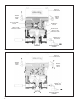
1. Install a “tee” at the AR‑2
™
valve’s service port and at
one of the delivery ports, then install a gauge in each.
2. Connect the tractor service and emergency “glad
hands” (hose couplings) to dummy connectors, or
alternatively, to a trailer. Build the tractor system air
pressure to governor cut‑out and make 4 to 5 full brake
applications. Check the air ttings at the AR‑2
™
valve
for leakage. Tighten as needed.
3. With the trailer supply valve (dash control with a red
octagonal button) and system park control (dash control
with a yellow diamond button) activated for tractor/trailer
operation, apply and release the brakes several times
and check for prompt application and release at each
wheel. If prompt reaction is noted at some, but not all
wheels, test the Bendix
®
M‑21
™
antilock modulator
between the AR‑2
™
valve and the brake chamber for
proper operation. If a “sluggish” response is noted at
all wheels, inspect for a kinked or obstructed air line
leading to or from the AR‑2
™
valve. If a complete release
of the brakes is noted at some, but not all wheels,
test the M‑21
™
antilock modulator between the AR‑2
™
valve and the brake chamber for proper operation. If
an incomplete release is noted at all wheels, inspect
for a kinked or obstructed air line leading to or from the
AR‑2
™
valve.
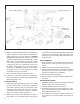
4. Check the AR‑2
™
valve’s differential pressure by
applying 10 psi to the service port and noting the
pressure registered at the delivery port. Subtract
delivery port pressure from the 10 psi service pressure
to obtain the differential. Compare the measured
differential with the pressure specied for the AR‑2
™
valve part number. NOTE: For AR‑2
™
valves not
incorporating a relay piston return spring the measured
differential should be approximately 4 psi. When a
spring is in use, the differential will be higher.
5. Make and hold a full (100 psi or greater) brake
application and note that full pressure is delivered to
the brake chambers.
6. Activate the dash mounted trailer supply valve for
bobtail tractor operation. Then make a slow brake
application, increasing the pressure at the AR‑2
™
valve
service port to 20 psi while watching the reaction at the
delivery port gauge. Note that delivery pressure rises to
approximately 5 to 10 psi and remains constant while
service pressure continues to rise to 20 psi. Release
the application.
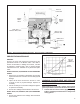
7. Make another brake application and slowly increase
the pressure at the AR‑2
™
valve service port to between
60 and 70 psi while observing the gauge installed at
the delivery port. Note that when service port pressure
rises to between 20 and 30 psi, delivery pressure begins
to rise above the initial pressure noted in step 6. The
rise of delivery pressure should be at a proportioned
rate of approximately 3 to 1. For example: Each 3
psi increase at the service port results in a delivery
pressure increase of 1 psi. At 70 psi service port
pressure, brake chamber pressure should be 15 to 25
psi.