
Owner manual


8
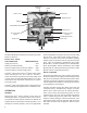
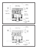
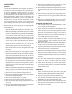
FIGURE 9 - TYPICAL BENDIX
®
CR-16
™
AIR BRAKE SYSTEM
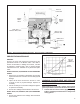
8. Make a full brake application and note that both test
gauges register the same pressure. IMPORTANT: If
during testing the service port pressure is SLOWLY
increased from approximately 70 psi to a full (100 psi
or greater) brake application, the Bendix
®
AR‑2
™
valve
MAY begin to cycle between an apply and exhaust
mode. This condition is normal while the AR‑2
™
valve
is transitioning from the proportioning mode to the
full delivery mode and will only occur if the service
application is SLOWLY increased as described.
Cycling will not occur or can be stopped by increasing
or decreasing service port pressure.
9. Remove the test gauges from the AR‑2
™
valve.
10. If the AR‑2
™
valve fails to perform as described it
should be replaced or repaired using genuine Bendix
replacement parts or kits.
LEAKAGE TESTS
1. Build the air system pressure to governor cut‑out. With
the dash mounted trailer supply valve activated for
tractor/trailer operation, apply a soap solution to both
exhaust ports (one in the cover and one in the body).
The leakage noted should not exceed a 1" bubble in
less than 3 seconds at either exhaust port.
2. Make and hold a full brake application and apply a
soap solution to both exhaust ports and around the
cover where it joins the body. The leakage noted should
not exceed a 1" bubble in less than 3 seconds at any
exhaust port with no leakage detected between the
cover and body.
VALVE REMOVAL
1. Park the vehicle on a level surface and block the wheels
and/or hold the vehicle by means other than the air
brakes.
2. Drain the air pressure from all vehicle reservoirs.
3. Identify, mark or label all air lines and wiring cables and
their respective connections on the valve or antilock
controller to facilitate ease of installation.
4. Disconnect all air lines and wiring.
5. Remove the AR‑2
™
valve and controller assembly from
the vehicle.
VALVE INSTALLATION
1. Install all air line ttings and plugs making certain thread
sealing material does not enter the valve.
2. Install the assembled valve on the vehicle.
3. Reconnect all air lines and wiring cables to the valve
and controller assembly using the identication made
during VALVE REMOVAL step 3.
4. After installing the valve and controller assembly, test
all air ttings for excessive leakage and tighten as
needed.
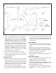
DASH CONTROL VALVES
BRAKE VALVE
BENDIX
®
M-21
™
MODULATORS
TRACTOR PROTECTION
BENDIX
®
AR-2
™
WITH
CONTROLLER