
Instruction Manual


2
OPERATION
GENERAL
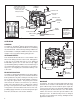
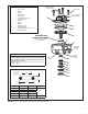
See Figure 2. The ATR-6
™
Antilock Traction Relay valve is
a service relay valve fi tted with a modifi ed cover containing
a Control Solenoid. Under normal operating conditions the
Control Shuttle, a small piston within the traction solenoid,
remains in its rest position, held by spring pressure.
ANTILOCK EVENTS
This document will describe the use of the ATR-6
™
valve
when used during a traction control event, although this
is only one role for which this valve is used. Advanced
Bendix ABS systems also use this valve to help supply
specifi c braking delivery for ABS events at a wider range of
speeds than typical traction control events occur, however
the process of energizing the solenoid and delivery of air
is the same.
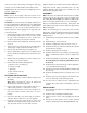
BRAKE APPLICATION
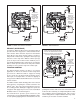
See Figure 3. During normal braking, as the driver applies
force to the brake pedal, air pressure is delivered from the
brake pedal to the relay valve control port. The air pressure
passes into the valve, past the Control Shuttle, and moves
the relay valve piston down. The piston pushes down
and contacts the exhaust seat of the inner (or ‘exhaust’)
portion of the inlet/exhaust valve, sealing off the exhaust
passage. As the piston moves further down, the outer (or
‘inlet’) portion of the inlet/exhaust valve moves off its seat,
permitting supply air from the reservoir to fl ow past the open
inlet valve, and into the service brake chambers.
BRAKE PEDAL
RESERVOIR
DELIVERY PORT
VALVE EXHAUST
RELAY VALVE
PISTON
CONTROL
SOLENOID
FIGURE 2 - SECTIONAL ATR-6
™
ANTILOCK TRACTION ASSEMBLY
CONTROL PORT
SUPPLY PORT
ANTILOCK
MODULATOR
VALVE
BRAKE
CHAMBER
TONE RING
WHEEL SPEED
SENSOR
Control Shuttle. The small
piston (shown in its normal
rest position). The arrow
indicates spring force
holding it in position.
FIGURE 3 - SERVICE BRAKE APPLICATION
The driver applies
the brakes. The
piston in the relay
valve moves
down allowing
the waiting air
pressure to pass
to the brake
chambers
RESERVOIR
BRAKE
CHAMBER
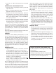
BALANCE
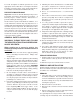
See Figure 4. The air pressure being delivered by the open
inlet valve also is effective on the bottom area of the relay
piston. When air pressure beneath the piston equals the
service air pressure above, the piston lifts slightly and the
inlet spring returns the inlet valve to its seat. The exhaust
remains closed as the service line pressure balances the
delivery pressure. As delivered air pressure is changed,
the valve reacts instantly to the change, holding the brake
application at that level.
INLET /
EXHAUST
VALVE
Diagram shows
a rear brake
application, but
this valve may
also be used for
front brakes