
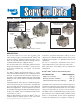
Instruction Manual


5
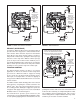
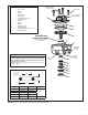
O-RING IDENTIFICATION
Key I.D. O.D. W
2 3.487 3.693
0.103
3 3.234 3.512
9 1.424 1.630
10 0.862 1.068
14 0.255 0.435 0.066
Key No. Description
1 . . . . . . Valve Cover
2 . . . . . . O-ring
3 . . . . . . O-ring
4 . . . . . . Relay Piston
5 . . . . . . Valve Body
6 . . . . . . Inlet & Exhaust Valve
7 . . . . . . Valve Retainer
8 . . . . . . Spring
9 . . . . . . O-ring
10. . . . . . O-ring
11. . . . . . Exhaust Cover
12. . . . . . Retaining Ring
13. . . . . . Differential Spring (If Used)
14. . . . . . Sealing O-ring
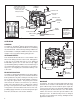
FIGURE 7 - ATR-6
™
EXPLODED VIEW AND O-RING IDENTIFICATION
DIFFERENTIAL SPRING
(CONTROLS CRACK PRESSURE*)
(Not used for most models.
See box below.)
13
11
CAP SCREW
1
5
6
2
4
3
12
10
9
8
7
VERTICAL
DELIVERY
PORTS
SUPPLY
PORT
HORIZONTAL
DELIVERY
PORTS
TRACTION
SOLENOID
See Below for O-ring Identifi cation Chart
Washer Identifying
Crack Pressure
SECTIONAL SIDE
VIEW SHOWING
HOW AN O-RING IS
MEASURED.
I.D."
W
O.D."
DIFFERENTIAL SPRINGS
*Crack Pressure is the amount of control pressure required by
the valve to initiate air delivery. For Crack Pressures other than
4 psi, a differential spring is used in the assembly to produce
the required valve response.
(Models designed to have a 4 psi Crack Pressure do not require a
differential spring.)
14