
Instruction Manual

6
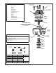
valve insert can be removed by removing the snap ring,
exhaust cover assembly and then inlet/exhaust valve.
Caution: Drain all reservoirs before attempting to remove
the inlet exhaust valve.
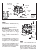
DISASSEMBLY
Note: Prior to disassembly, mark the location of the
mounting bracket (not shown) to the cover and the cover
to the body.
CAUTION: The valve body may be lightly clamped in a
bench vise during disassembly, however, over-clamping will
result in damage to the valve and result in leakage and/or
malfunction. If a vise is to be used, position the valve so
that the jaws bear on the supply ports on opposing sides
of the valve’s body.
1. Remove the four cap screws (and I.D. washer) securing
the mounting bracket and cover to the body. Retain
the cap screws and washer for reuse. Remove the
electrical connection to the traction solenoid.
2. Remove and discard sealing rings (2 and 14) from the
cover (1).
3. Remove piston (4) from the body (5) [and differential
spring (13) if used]. Retain these items for reuse.
4. Remove and discard O-ring (3) from piston (4).
5. Depress and hold the exhaust cover assembly (11) and
remove and discard retaining ring (12) from the valve
body (5).
6. Slowly release the holding force on the exhaust cover
assembly (11) to relax the spring.
7. Remove and discard the following parts:
a. Exhaust cover assembly (11)
b. O-rings (9 & 10)
c. Spring (8)
d. Inlet exhaust valve (6)
e. Retainer (7)
CLEANING AND INSPECTION
1. Wash all metal parts in mineral spirits and dry them
thoroughly.
(Note: When servicing R-12
®
valves, all springs and
all rubber parts should be replaced.)
2. Inspect all metal parts for deterioration and wear, as
evidenced by scratches, scoring and corrosion.
3. Inspect the exhaust valve seat on the relay piston for
nicks and scratches which could cause excessive
leakage.
4. Inspect the inlet valve seat in the body for scratches
and nicks, which could cause excessive leakage.
5. Inspect the check valve seat in the R-12
®
valve cover
and make sure all internal air passages in this area are
open and clean and free of nicks and scratches.
Replace all parts not considered serviceable during these
inspections and all springs and rubber parts. Use only
genuine Bendix replacement parts, available from any
authorized Bendix parts outlet.
ASSEMBLY
Note: All torques specifi ed in this document are assembly
torque and can be expected to fall off slightly after
assembly. Do not re-torque after initial assembly torque
fall. For assembly, hand wrenches are recommended.
Prior to assembly, lubricate all O-rings, O-ring bores and
any sliding surface with a silicone lubricant equivalent to
Dow Corning #10.
Wash all remaining parts in mineral spirits and dry
thoroughly. Using the lubricant provided in this kit, lightly
lubricate all O-rings, O-ring grooves, body bores and any
sliding surfaces.
1. Install O-rings (9 & 10) in the exhaust cover assembly
(11).
2. Install O-ring (3) on the piston (4).
3. Install the sealing rings (2 and 14) on the cover (1).
4. Install the retainer (7) on the inlet exhaust valve (6) and
insert both in the body (5).
5. Install the spring (8) in the body (5).
6. Install the exhaust cover assembly (11) in the body (5).
Depress and hold the exhaust cover assembly in the
body.
7. Install retaining ring (12) in the body (5). Make certain
the retaining ring is completely seated in the groove
in the body.
8. Install the piston (4) in the body (5). Where applicable,
re-use the differential spring (13).
9. Referring to the marks made during disassembly, install
the cover (1).
10. Install the mounting bracket (not shown) on the cover
(1).
11. Install the four cap screws with the I.D. washer in the
cover (1) and torque to 80-100 inch pounds.
12. Test the valve as outlined in the Operational and
Leakage Test section before returning the vehicle to
service.
INSTALLATION
1. Clean and inspect all air hoses for damage and replace
as necessary.
2. Install the valve and tighten mounting bolts.
3. Connect air hoses to the valve (plugging any unused
ports).
4. Reconnect the wire harness to the traction solenoid
using the identifi cation made during REMOVAL step.