
Instruction Manual


2
INSTALLATION
The DRO valve can be installed in two confi gurations,
series or parallel.
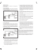
Series Confi guration
The series confi guration, shown in Figure 3, allows all the
compressor discharge air to pass through the valve and
into the dryer or reservoir.
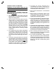
Parallel Confi guration
The parallel confi guration, shown in Figure 4, allows the
DRO unloader valve to be mounted using a branch circuit.
This branch circuit provides the fl exibility of installing the
unloader valve in a more convenient location. The branch
line should not run uphill or have kinks or sharp bends that
may trap condensed liquids.
1. Locate a position in the discharge line of the
compressor where the DRO valve can be mounted.
The valve must be mounted at the same height or
below the compressor outlet.
2. Secure the DRO valve using 5/16” grade 5 or higher
bolts. It is not recommended to install the valve directly
on to the engine or compressor.
3. For series installation, install a discharge line from the
compressor to the DRO valve, as shown in Figure 3.
For parallel installation add another discharge line
into the existing compressor discharge line using a
tee fi tting. Connect the opposite end of this new line
to the DRO unloader valve as shown in Figure 4. The
valve must be at the same height or lower than the
discharge line.
4. For a series confi guration, the delivery line out of the
DRO should be connected to the air brake dryer or
reservoir tank.
5. For a parallel confi guration, the delivery port out of the
DRO must be plugged.
6. The supply and delivery ports are 22 mm metric
threads. The control port is 12 mm metric threads.
Consult a fi tting supplier for conversion fi ttings.
7. Make sure there is a line from the governor unloader
port to the DRO valve control port.
8. Test all connections for leaks.
9. Start the engine and allow the system to reach cut-
out pressure. The valve should open allowing air to
exit the exhaust port. A silencer, shown in Figure 2, is
recommended to reduce the noise level out of the DRO
valve when exhausting. Bendix provides a silencer that
snaps onto the exhaust port the DRO.
10. Fan the brakes until system cut-in is reached. The
DRO valve exhaust should shut allowing the air brake
system pressure to increase until cut-out pressure is
reached.
Note: The operating range of the DRO unloader valve is
from -40°F to 300°F. The DRO valve must be installed with
suffi cient discharge line length to prevent the air dryer inlet
temperature from exceeding 160°F.
To prevent failure or freeze-ups, the control air into the
DRO valve must be free of liquid water and fl uids and the
maximum inlet pressure to the DRO valve is 174 PSI.
TO THE
CONTROL
PORT OF THE
AIR DRYER
TO THE SUPPLY
PORT OF THE
AIR DRYER
DRO
UNLOADER
VALVE
FROM THE
RESERVOIR
FIGURE 3 - SERIES CONFIGURATION
GOVERNOR
COMPRESSOR
TO THE
CONTROL
PORT OF THE
AIR DRYER
TO THE SUPPLY
PORT OF THE AIR
DRYER
DRO
UNLOADER
VALVE
FROM THE
RESERVOIR
FIGURE 4 - PARALLEL CONFIGURATION
GOVERNOR
PORT 21 MUST
BE PLUGGED