
Instruction Manual

3
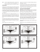
SERVICE CHECKS
OPERATING TEST
With system charged, make several foot valve applications and note
each time an application is made, an exhaust of air occurs at the exhaust
port of the drain valve. If no air comes out, push the wire stem. If no air
comes out, there may be a plugged fi lter in the adapter which should
be removed and discarded.
LEAKAGE TEST
With system charged and pressure stabilized in system, there should
be no leaks at the drain valve exhaust. A constant slight exhaust of air
at the drain valve exhaust could be caused by excessive leakage in
the air brake system.
If the Bendix
®
DV-2
™
automatic drain valve does not function as
described or if leakage is excessive, it is recommended that it be
replaced with a new or remanufactured unit or repaired with genuine
Bendix parts.
INSTALLING AND REMOVING
REMOVING
Block and hold vehicle by means other than air brakes. Drain air
system.
Disconnect heater wire if valve is so equipped. Remove automatic
reservoir drain valve.
DISASSEMBLY
Remove 4 cap screws and lock washers. Remove cover and sealing
ring.
NOTE: The heater and thermostat of the DV-2
™
valve’s so equipped
are not serviceable. If the heater or thermostat has failed, the
entire cover must be replaced. Do not remove the thermostat
cover plate. It is moisture sealed and removal could result in
early thermostat failure.
Remove valve guide.
Remove inlet and exhaust valve.
Remove adapter and fi lter assembly (if fi lter present).
Remove fi lter retainer (if any).
Remove fi lter (if any).
INSTALLING
Block and hold vehicle by means other than air brakes. Drain air
system.
To avoid early fouling at the DV-2
™
valve, thoroughly fi nish and clean
the reservoir before installing the drain valve.
Aerate any tank thoroughly if any solvents have been used in the
cleaning process.
IMPORTANT
When installing a DV-2
™
drain valve equipped with a heater and
thermostat, fi rst determine if the vehicle electrical system is 12 or 24
volt, and that the heater/thermostat unit is of the same voltage. The #14
gauge lead wire on the valve should be connected to the “on” position of
the engine control or ignition switch. Use an 8 amp fuse for one valve,
a 15 amp fuse for two valves, and a 20 amp fuse for three valves. All
electrical connections must be waterproof.
CLEANING AND INSPECTION
Cleaning solvent may be used on metal parts. Rubber parts should
be wiped clean.
Inspect all parts for wear or deterioration. Discard fi lter screen if
present.
Replace all parts not considered serviceable during these
inspections.
Bendix Field Maintenance Kit 282134 contains all parts necessary for
servicing all models of the DV-2
™
valve.
ASSEMBLY
Before assembling the valve, apply a light fi lm of grease on inlet valve
seat.
DO NOT APPLY OIL TO THE INLET AND EXHAUST VALVE.
Place sealing ring in groove of cover.
Place valve guide over inlet and exhaust valve.
Place valve guide and inlet and exhaust assembly into cover (wire will
project through exhaust port).
Place body on cover and install cap screws and lockwashers. Install
adapter or pipe nipple in appropriate port.
Install drain valve in reservoir and reconnect heater wire if drain valve
is so equipped.
NOTE: Covers on the standard and heated drain valves can be
interchanged.
TESTING REBUILT AUTOMATIC RESERVOIR DRAIN
VALVE
Perform “Operating and Leakage Checks” as outlined in this section.