
User guide
10
4. Remove as much contamination as possible from the
assembly's exterior. Keep the contamination away from
the open ports.
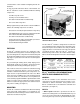
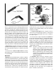
5. Note and mark the position of the EC-16
™
controller
relative to the valve it is mounted on. Remove and retain
the four cap screws that secure the EC-16
™
controller
to the valve. Then separate the EC-16
™
controller from
the valve.
BRACKET MOUNTED EC-16
™
CONTROLLER
1. Disconnect the electrical connector(s) from the EC-16
™
controller.
2. Note and mark the mounting position of the EC-16
™
controller on the vehicle. Loosen, remove and save the
nuts on the mounting hardware that attaches the
EC-16
™
controller bracket to the vehicle. Remove the
EC-16
™
controller and bracket from the vehicle.
3. Remove and retain the four cap screws that secure the
EC-16
™
controller to the bracket. Separate the EC-16
™
controller from the bracket.
4. Perform the "Initial Start up Procedure" in the
TROUBLESHOOTING section to assure proper system
operation.
INSTALLING THE EC-16
™
CONTROLLER
EC-16
™
CONTROLLER MOUNTED ON
ANTILOCK RELAY VALVE OR ANTILOCK
TRACTION RELAY VALVE
1. After noting the relationship of the positioning marks
made prior to disassembly, position and secure the
EC-16
™
controller to the valve using the four cap screws.
Torque the cap screws to 50-80 Ibs. in.
2. Mount the assembled EC-16
™
controller and antilock
relay valve on the vehicle and orient it in the position
marked before removal.
3. Reconnect all air lines to the assembly.
4. Reconnect the electrical connector(s) to the EC-16
™
controller.
5. Test the valve for operation and leakage prior to placing
the vehicle in service.
6. Perform the "Initial Start Up Procedure" in the
TROUBLESHOOTING section to assure proper system
operation.
BRACKET MOUNTED EC-16
™
CONTROLLER
1. Secure the EC-16
™
controller to its bracket using the
four cap screws. Torque to 50-80 Ibs. in.
2. After noting the positioning marks, mount the EC-16
™
controller on the vehicle using the mounting hardware
retained during removal.
3. Connect the electrical connector(s) to the EC-16
™
controller.
4. Perform the "initial Start up Procedure" in the
TROUBLESHOOTING section to assure proper system
operation.
DIAGNOSING AND LOCATING A SYSTEM
PROBLEM
GENERAL
The EC-16
™
controller contains self test and diagnostic
circuitry that continuously checks for proper operation of
the entire antilock/traction system, including wiring continuity.
The EC-16
™
controller is programmed at the factory to
accommodate the needs of the vehicle and the customer's
desires. All EC-16
™
controllers are not factory programmed
with the traction control feature, in which case antilock only
will be active. The newer, self configuring EC-16
™
controller
can be reconfigured by the end user to include traction
control. A vehicle equipped with traction control can generally
be identified by noting the presence of a dashmounted
condition lamp, a disable switch (for the traction control
system) and a traction solenoid located above the relay valve.
Separate dash lamps, controlled by the EC-16
™
controller,
advise the driver of the condition of the entire antilock/traction
system. The condition of specific components is provided
by a series of labeled, light emitting diodes (LEDs) in the
EC-16
™
controller housing. No special tools or equipment
are needed to read or interpret the EC-16
™
controller
diagnostic display. It should be noted that the EC-16
™
controller diagnostics display is separate from the antilock
and traction condition lamps on the dash. With this
separation, the driver is aware of any problems that occur
but is not confused by diagnostic information.
When the controller senses an erroneous condition, it stores
the condition in memory, disables the antilock or traction
function, and illuminates the dash mounted condition lamp
and the appropriate diagnostic LEDs on the EC-16
™
controller. The failure condition is truly stored and is not
cleared by loss of power to the EC-16
™
controller. The LEDs
will relight when power is restored and remain illuminated
until the failure is corrected. After the actual problem is
corrected, maintenance personnel can clear or reset the
EC-16
™
controller diagnostics by holding a small magnet
over the RESET point in the diagnostics display.
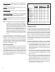
DIAGNOSTIC LEDS
There are ten LEDs plus a magnetically actuated reset switch
in the EC-16
™
controller diagnostic display. The first six LEDs
locate a problem to a specific area of the vehicle, and the
next three indicate the problem component or its wiring.
The LEDs are software driven and are either ON or OFF
depending upon their monitor function. (Note: right and left,
front and rear are determined from the driver's seat.)