
User guide

3
contained in the section entitled "Configuring The EC-16
™
Controller".
In order to provide full vehicle wheel control antilock, the
EC-16
™
controller is used in combination with the following
components:
- Four wheel speed sensors
- Four air pressure modulator valves
- One dash mounted antilock condition lamp
- One service brake relay valve
When programmed to provide traction control in addition to
antilock, the following components are added:
- One traction solenoid (incorporated into the relay valve)
- Two additional wheel speed sensors (optional for tandem
drive vehicles with differential braking feature)
- One dash mounted traction condition lamp
- Serial connection to engine control module (for vehicles
programmed for torque limiting feature)
- Traction disable wiring and switch
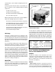
PHYSICAL
The EC-16
™
controller electronics are contained in a die
cast aluminum housing and are environmentally protected
by a self healing silicone compound. The metal housing and
the design of the digital electronics are intended to provide a
high degree of protection from radio and electromagnetic
interference.
The patented light emitting diode (LED) display and a
magnetically actuated reset switch is incorporated in the
housing for troubleshooting and diagnostic purposes.
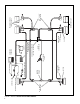
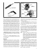
Two electrical connectors located in the controller housing
opposite the diagnostic display, connect the EC-16
™
controller to antilock and traction system components: one
30 pin and one 18 pin Packard Electric 150 series "Metri
pack" connector. In addition to these two housing mounted
connectors, the EC-16
™
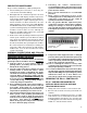
controller also uses a 2 pin Deutsch
connector when programmed with the optional traction control
feature. The 2 pin connector is linked to a traction solenoid,
which is located in the upper portion of the antilock traction
relay valve assembly. (See Figure 3.)
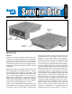
MOUNTING
The EC-16
™
controller is available in two different mounting
styles. One model, shown in Figure 1, is a stand-alone. It is
intended for bracket mounting to a frame member and is not
attached to an antilock relay valve.
EC-16
™
CONTROLLER INFORMATIONAL
INPUTS AND COMMAND OUTPUTS
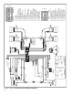
GENERAL
The EC-16
™
controller receives information from several
components in system and, based on these inputs, issues
commands or delivers information. Some portions of the
EC-16
™
controller both receive and deliver commands and
information. (See Figure 4.)
INPUTS
- Wheel speed information is provided to the EC-16
™
controller via a wiring harness from individual wheel speed
sensors at or in the vehicle wheels. Working with an exciter
or tone ring, wheel speed sensors provide information to the
2-PIN CONNECTOR
(TO TRACTION SOLENOID)
ANTILOCK TRACTION
ASSEMBLY
EC-16
™
CONTROLLER
TRACTION
SOLENOID
TRACTION
RELAY
FIGURE 3 - EC-16
™
CONTROLLER W/ANTILOCK
TRACTION RELAY VALVE
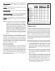
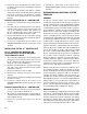
AntiLock Added Function Vehicle Designation
Valve Provided Application (Valve + EC-16)
AR 1 None All CR 17 Controller Relay
AR 2 Bobtail Brake Tractors Only CR 18 Controller Relay
Proportioning
ATR-1 Traction All AT 1 AntiLock Traction
ATR 2 Traction & Bobtail Tractors Only AT 2 AntiLock Traction
Brake Proportioning
The other EC-16
™
controller is designed to be mounted on
one of four different valves. All of the valves provide the relay
function and replace the standard service relay on antilock
equipped vehicles. In some instances the valves also provide
specialized functions. When the EC-16
™
controller is
mounted on any of these valves, the result is a final assembly
with its own model designation. Refer to the chart and figure
3.